2005 Infiniti G35 Fuse Box Diagram
For the intermediate DIYer tackling electrical issues or planning modifications on a 2005 Infiniti G35, understanding the fuse box diagram is absolutely crucial. It's the roadmap to your car's electrical system, allowing you to diagnose problems, perform repairs, and even safely add aftermarket accessories. Without it, you're essentially working blind, increasing the risk of damaging sensitive components and potentially causing a fire. This article will break down the intricacies of the 2005 G35's fuse box, providing you with the knowledge to confidently navigate its circuitry.
Purpose: Your Electrical System's Rosetta Stone
The fuse box diagram serves multiple critical purposes. Primarily, it's your go-to guide for identifying the correct fuse or relay associated with a specific electrical component. This is invaluable when troubleshooting issues like a malfunctioning power window, a dead cigarette lighter, or a non-functioning headlight. It helps prevent guesswork and ensures you're working on the right circuit.
Beyond repairs, the diagram is also essential for safely adding aftermarket accessories, such as amplifiers, LED lights, or aftermarket security systems. By understanding the fuse ratings and circuit layouts, you can tap into the correct power sources without overloading circuits or damaging existing wiring. This is paramount for modders who want to customize their G35 without compromising its electrical integrity.
Key Specs and Main Parts
The 2005 Infiniti G35 actually has two primary fuse boxes:
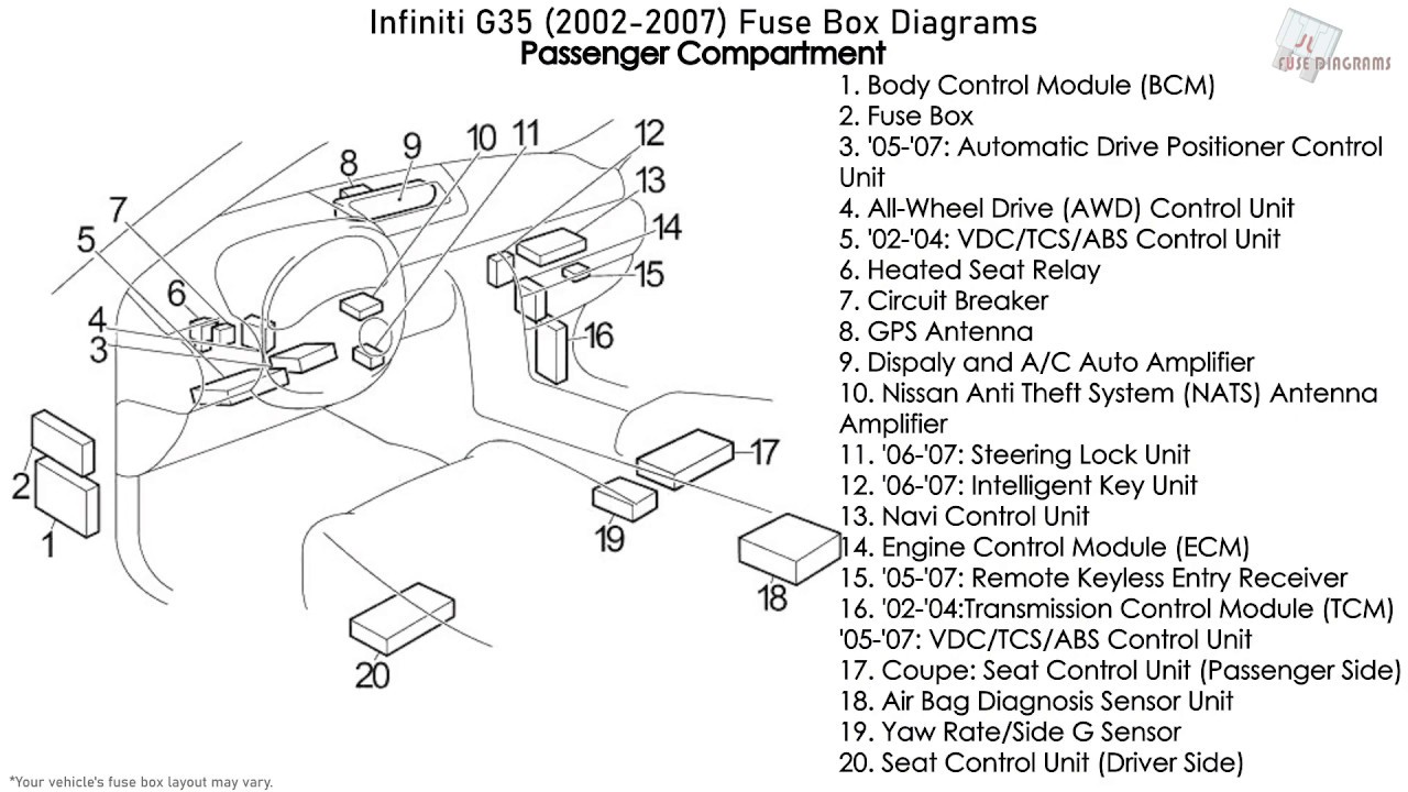
- Interior Fuse Box: Located usually underneath the driver's side dashboard near the footwell. This box handles most of the interior components, accessories, and some engine-related functions.
- Engine Compartment Fuse Box: Situated in the engine bay, typically near the battery or firewall. This box primarily manages the car's engine control, starting, charging, and critical exterior lighting systems.
Each fuse box contains:
- Fuses: These are the sacrificial links that protect circuits from overcurrent. They're rated in Amperes (Amps), indicating the maximum current they can handle before blowing. Common ratings are 5A, 7.5A, 10A, 15A, 20A, 25A, 30A, 40A.
- Relays: These are electromagnetic switches that control higher-current circuits using a low-current signal. They're used for components like headlights, fuel pumps, and starter motors.
- Wiring: Connects the fuses and relays to the various components. Wire gauge (thickness) is crucial for current carrying capacity. Using wires that are too thin can result in overheating and fire.
- Bus Bars: Metal strips that distribute power to multiple fuses or relays.
- Cover/Diagram: Most importantly, the cover of each fuse box should have a diagram that identifies the function of each fuse and relay. This is often a sticker or a molded-in legend. Unfortunately, these stickers can sometimes become damaged or go missing over time. That's why having a digital copy is important.
It's crucial to note the Ampere rating of each fuse. Replacing a blown fuse with one of a higher rating is extremely dangerous, as it can bypass the circuit protection and lead to overheating, melting wires, and potentially a fire. Always use the same Amp rating or a lower rating when replacing a fuse.
Symbols: Deciphering the Electrical Language
Fuse box diagrams use symbols and abbreviations to represent different electrical components and circuits. Understanding these symbols is key to interpreting the diagram correctly.
- Lines: Lines represent wires connecting the various components. Thicker lines might indicate wires with higher current-carrying capacity.
- Colors: Wire colors are often indicated on more detailed wiring diagrams (separate from the fuse box diagram) and help in tracing specific circuits. The fuse box diagram itself often doesn't include wire colors, but understanding wire color codes is a valuable skill for electrical troubleshooting.
- Icons: Various icons represent different components. Here are a few common ones:
- Rectangle with a squiggly line inside: Resistor.
- Circle with an "X" inside: Lamp or light bulb.
- Coil symbol: Inductor or relay coil.
- M inside a Circle: Motor.
- Fuse Symbol: A line broken in the middle indicates a fuse.
- Abbreviations: Common abbreviations include:
- ECU: Engine Control Unit (the car's computer).
- ABS: Anti-lock Braking System.
- A/C: Air Conditioning.
- IGN: Ignition.
- ST: Starter.
- RR: Rear.
- FR: Front.
Pay close attention to the diagram's legend or key, which will define the specific symbols and abbreviations used. These can sometimes vary slightly depending on the specific edition of the service manual.
How It Works: The Electrical Flow
The fuse box acts as a central distribution point for electrical power throughout the vehicle. Power from the battery is routed through the fuse box, and each circuit is protected by a fuse. When an electrical component draws excessive current (due to a short circuit or overload), the fuse blows, interrupting the circuit and preventing damage to the wiring and components. The relay is controlled by the ECU to close or open the circuit for the components.
Imagine it like this: The battery is a reservoir of water, and the electrical circuits are pipes leading to different faucets (components). The fuses are like small dams along those pipes. If too much water tries to flow through a pipe, the dam breaks, preventing the pipe from bursting. The relays act as valves that let the current to pass or stop.
Real-World Use: Basic Troubleshooting Tips
Here's how you can use the fuse box diagram for basic troubleshooting:
- Identify the Problem: Determine which component is malfunctioning (e.g., the radio isn't working).
- Locate the Fuse: Consult the fuse box diagram to identify the fuse associated with that component.
- Inspect the Fuse: Visually inspect the fuse. If the thin wire inside is broken, the fuse is blown. You can also use a multimeter to test for continuity. A blown fuse will show no continuity.
- Replace the Fuse: Replace the blown fuse with a new fuse of the same Ampere rating.
- Test the Component: Check if the component now works. If it does, the problem was likely a blown fuse.
- If the Fuse Blows Again: If the new fuse blows immediately or shortly after replacement, there's likely a short circuit or overload in the circuit. Further diagnosis is required, which may involve tracing the wiring, inspecting the component itself, or consulting a professional mechanic.
Safety: Handle with Care
Working with electrical systems can be dangerous. Here are some safety precautions:
- Disconnect the Battery: Before working on any electrical components, disconnect the negative terminal of the battery to prevent accidental short circuits.
- Use Insulated Tools: Use tools with insulated handles to protect yourself from electric shock.
- Never Bypass Fuses: Never bypass a fuse by using a wire or other conductive material. This eliminates the circuit protection and can lead to a fire.
- Identify High-Current Circuits: Be especially careful when working with high-current circuits like the starter motor, alternator, and fuel pump. These circuits can deliver a dangerous electric shock.
- When in Doubt, Consult a Professional: If you're not comfortable working with electrical systems, consult a qualified mechanic.
Crucially, never work on the electrical system while the engine is running. And always double-check your work before reconnecting the battery. Safety should be your top priority.
We understand how vital access to the fuse box diagram is for your work on your Infiniti G35. We have the complete 2005 Infiniti G35 fuse box diagram available for download. This diagram provides detailed information, including fuse locations, Ampere ratings, and the components they protect.