2005 Jeep Grand Cherokee Radio Wiring Diagram
So, you’re wrestling with the radio in your 2005 Jeep Grand Cherokee, huh? Whether you're upgrading to a modern head unit, troubleshooting a malfunctioning factory system, or simply trying to understand what's going on behind the dashboard, a reliable wiring diagram is absolutely essential. This guide breaks down the 2005 Jeep Grand Cherokee radio wiring diagram, giving you the knowledge to tackle your audio project with confidence.
Why This Diagram Matters
Let’s be real. Car audio systems can be a tangled web of wires. Without a clear diagram, you're essentially flying blind. Here's why having the 2005 Jeep Grand Cherokee radio wiring diagram is so crucial:
- Repairs: Identifying faulty connections, short circuits, or damaged wires becomes significantly easier. Pinpointing the source of your radio problems saves you time and frustration.
- Upgrades: Installing an aftermarket head unit, amplifier, or speakers requires understanding the factory wiring. Connecting to the wrong wires can damage your new equipment or even the vehicle's electrical system.
- Learning: Even if you’re not actively working on the system, studying the wiring diagram provides valuable insight into how the radio integrates with other vehicle components, such as the speakers, antenna, and vehicle's computer (ECU).
- Documentation: Having a record of the original wiring is useful for future maintenance and repairs. It also helps if you ever decide to sell the vehicle.
Key Specs and Main Parts
Before we dive into the diagram specifics, let’s cover some essential specs and components of the 2005 Jeep Grand Cherokee radio system. Understanding these will help you interpret the wiring diagram accurately.
- Voltage: The system operates on a 12-volt DC (Direct Current) electrical system. This is standard for most automotive applications.
- Radio Type: The Grand Cherokee came with several radio options, from basic AM/FM/CD players to more advanced units with features like navigation and satellite radio. The wiring may slightly differ depending on the specific radio installed.
- Speakers: The vehicle typically has speakers located in the front doors, rear doors (if equipped), and sometimes in the dashboard. Knowing the speaker locations helps you trace the corresponding wires on the diagram.
- Antenna: The antenna receives radio signals. Its connection is crucial for good radio reception.
- Amplifier (Optional): Some Grand Cherokees came with a factory amplifier, which boosts the audio signal to the speakers. If your vehicle has an amplifier, the wiring diagram will include its connections.
Here are the main parts that will appear on the wiring diagram:
- Head Unit (Radio): The central control unit for the audio system.
- Speakers: The components that produce sound.
- Antenna: Receives radio signals.
- Amplifier (If equipped): Boosts the audio signal.
- Wiring Harnesses: Groups of wires bundled together with connectors.
- Connectors: Plugs that connect the wiring harnesses to the various components.
- Ground Points: Points where wires are connected to the vehicle's chassis for grounding. Proper grounding is essential for electrical circuit function.
- Fuses: Protective devices that prevent damage from overcurrent.
Decoding the Symbols
Wiring diagrams use standardized symbols to represent electrical components and wiring connections. Understanding these symbols is vital for interpreting the diagram correctly.
Lines and Colors
- Solid Lines: Represent wires. The thickness of the line usually doesn't indicate wire gauge but rather emphasizes the line for clarity.
- Dotted Lines: Often indicate shielded wires or wires that are part of a harness shared by multiple systems.
- Color Codes: Each wire is assigned a color code (e.g., RD for Red, BK for Black, YL for Yellow). The color code is typically printed next to the wire on the diagram. Pay close attention to the color code, as it’s the primary way to identify individual wires.
Component Symbols
- Resistor: A zig-zag line.
- Capacitor: Two parallel lines.
- Inductor: A coiled line.
- Ground: A symbol that looks like an upside-down tree or a series of horizontal lines decreasing in length.
- Fuse: A line with a small "S" shape inside.
- Switch: A line that can be opened or closed to control the flow of electricity.
- Diode: A triangle with a line at the end.
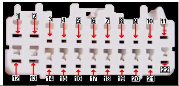
- Connector: Usually depicted as a square or rectangle with numbered or lettered pins. These numbers correspond to the pin numbers on the actual connector.
Other Markings
- Wire Gauge: The wire gauge (e.g., 18 AWG) may be indicated next to the wire. This is important for selecting the correct size wire for repairs or upgrades.
- Circuit Numbers: Each circuit is assigned a number, which helps identify the circuit's function and trace its path through the system.
- Ground Locations: Ground points are often labeled with a letter and number (e.g., G101). These labels indicate the specific location of the ground connection on the vehicle's chassis.
How It Works
The 2005 Jeep Grand Cherokee radio system works by receiving power from the vehicle's battery, processing audio signals, and sending those signals to the speakers. The head unit receives power from the battery via the ignition switch and a constant power source. The ignition switch allows the radio to turn on and off with the vehicle, while the constant power source maintains the radio's memory settings (e.g., preset stations). The head unit also receives signals from the antenna and various inputs such as CD players or auxiliary ports.
The head unit processes the audio signals and sends them to the speakers or, if equipped, to an amplifier. The amplifier boosts the signal and sends it to the speakers. The speakers convert the electrical signals into sound waves. The wiring diagram shows how all these components are interconnected and how power and signals flow through the system.
Real-World Use: Basic Troubleshooting Tips
Now, let's put this knowledge to use. Here are some common radio problems and how the wiring diagram can help you diagnose them:
- No Power: Check the fuses related to the radio. Use the wiring diagram to identify the correct fuse location. If the fuse is blown, replace it with one of the correct amperage. If the fuse continues to blow, there is likely a short circuit in the wiring.
- No Sound: Check the speaker connections. Use the wiring diagram to identify the speaker wires and ensure they are properly connected to the head unit or amplifier. Also, check the speaker themselves with an multimeter to see if they are still functional.
- Poor Reception: Check the antenna connection. Use the wiring diagram to locate the antenna wire and ensure it is securely connected to the head unit. Also check to see if the antenna wire has a good connection to the physical antenna.
- Intermittent Problems: Loose or corroded connections can cause intermittent problems. Use the wiring diagram to identify all the connections in the radio system and inspect them for damage.
When troubleshooting, always use a multimeter to check for voltage, continuity, and resistance. This will help you pinpoint the source of the problem. Always disconnect the negative battery terminal before working on the electrical system to prevent short circuits and electrical shock.
Safety First
Working with automotive electrical systems can be dangerous. Here are some essential safety precautions:
- Disconnect the Battery: Always disconnect the negative battery terminal before working on any electrical components. This prevents accidental short circuits and electrical shock.
- Use Proper Tools: Use insulated tools designed for automotive electrical work.
- Avoid Water: Never work on electrical systems in wet conditions.
- Be Careful with Airbags: Airbags are explosive devices. Avoid disturbing any airbag wiring or components. Consult a professional if you need to work near airbags.
- Fuses: Never replace a fuse with one of a higher amperage rating. This can overload the circuit and cause a fire.
The radio and its associated wiring are relatively low-voltage, but other components in the vehicle's electrical system can carry high voltage. Be particularly careful when working near the ignition system, charging system, and battery.
We have the full 2005 Jeep Grand Cherokee radio wiring diagram available for download. With this guide and the diagram in hand, you'll be well-equipped to tackle your audio project with confidence and accuracy. Good luck!