2005 Jeep Liberty 3.7 Engine Diagram
For the intermediate DIY mechanic or Jeep enthusiast tackling repairs, modifications, or simply seeking a deeper understanding of their 2005 Jeep Liberty, a detailed engine diagram is an indispensable tool. Specifically, the engine diagram for the 3.7L PowerTech V6 is crucial. This article serves as your comprehensive guide to interpreting and utilizing this diagram, ensuring you can confidently navigate the intricacies of your Liberty's powerplant. We'll break down the key components, explain the diagram's symbology, and provide practical troubleshooting tips, all while prioritizing safety.
Purpose of the 2005 Jeep Liberty 3.7L Engine Diagram
The engine diagram serves several critical purposes:
- Diagnosis and Repair: It allows you to pinpoint the location of specific components, aiding in diagnosing engine problems. Instead of blindly searching, you can quickly identify sensors, actuators, and other parts that might be causing issues.
- Component Identification: It helps you correctly identify parts when ordering replacements. Misidentification can lead to delays and incorrect repairs.
- Wiring and Vacuum Line Tracing: The diagram often includes wiring schematics and vacuum line routing, which is essential for troubleshooting electrical and vacuum-related issues.
- Modification and Upgrades: If you're planning any modifications or upgrades, the diagram provides a visual layout of the engine, helping you understand the potential impact of your changes.
- Educational Tool: Simply put, it is a fantastic tool for learning more about your vehicle and how all the components work together!
Key Specs and Main Parts of the 3.7L PowerTech V6
Before diving into the diagram, let's cover some basic information about the 3.7L PowerTech V6 engine:
- Configuration: V6 (six cylinders arranged in a V-shape)
- Displacement: 3.7 Liters (226 cubic inches)
- Valve Train: SOHC (Single Overhead Camshaft) – A single camshaft per cylinder bank operates the valves.
- Horsepower (approx.): Around 210 hp @ 5200 rpm (depending on specific model year and tuning)
- Torque (approx.): Around 235 lb-ft @ 4000 rpm (depending on specific model year and tuning)
- Fuel Injection: Sequential Multi-Port Fuel Injection (SMPI) – Fuel is injected into each cylinder's intake port separately.
Key components typically included in an engine diagram for the 3.7L engine:
- Cylinder Head(s): Houses the valves, camshaft, and related components.
- Engine Block: The main structure of the engine, containing the cylinders.
- Pistons: Reciprocating components within the cylinders, driven by combustion.
- Connecting Rods: Connect the pistons to the crankshaft.
- Crankshaft: Converts the reciprocating motion of the pistons into rotational motion.
- Intake Manifold: Distributes air to the cylinders.
- Exhaust Manifold: Collects exhaust gases from the cylinders.
- Throttle Body: Controls the amount of air entering the engine.
- Fuel Injectors: Spray fuel into the intake ports.
- Ignition Coils: Provide the high-voltage spark to ignite the air-fuel mixture.
- Spark Plugs: Ignite the air-fuel mixture in the cylinders.
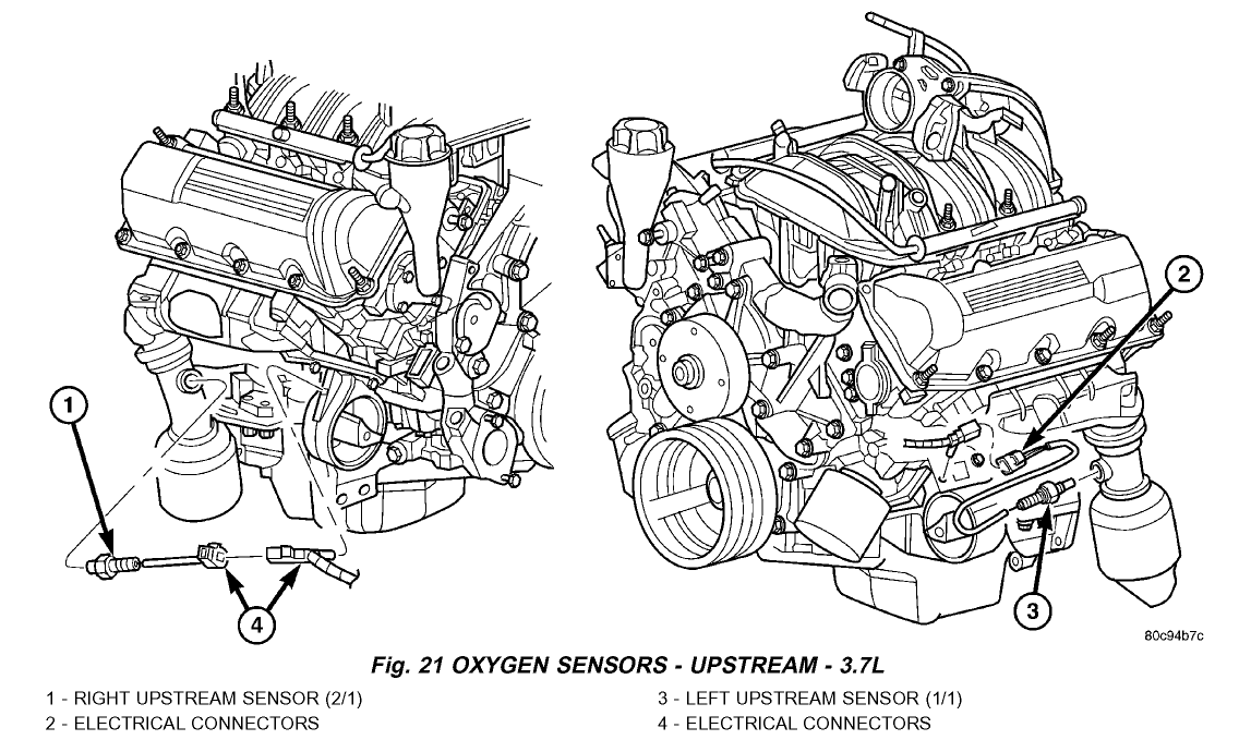
- Sensors: Crucial for engine management; includes the Crankshaft Position Sensor (CKP), Camshaft Position Sensor (CMP), Manifold Absolute Pressure (MAP) sensor, Oxygen (O2) sensors, and Coolant Temperature Sensor (CTS).
- Water Pump: Circulates coolant to regulate engine temperature.
- Oil Pump: Circulates oil to lubricate engine components.
- Alternator: Generates electricity to power the vehicle's electrical system.
- Starter Motor: Cranks the engine to initiate combustion.
Understanding the Symbols and Legends
Engine diagrams use a standardized set of symbols and legends to represent different components and their connections. These symbols can vary slightly depending on the specific diagram, so always refer to the accompanying legend.
- Solid Lines: Typically represent mechanical connections, such as hoses, pipes, or structural elements.
- Dashed Lines: Often indicate vacuum lines or other low-pressure connections.
- Dotted Lines: May represent wiring harnesses or signal paths.
- Colors: Wiring diagrams use colors to identify specific wires. For example, a red wire might represent a power supply, while a black wire represents a ground. The legend will specify the color code.
- Component Symbols: Each component has a specific symbol. For example, a resistor might be represented by a zigzag line, while a capacitor might be represented by two parallel lines.
- Arrows: Indicate the direction of fluid flow (e.g., coolant, oil).
Pay close attention to the legend! It is the key to accurately interpreting the diagram. A well-labeled diagram is your best friend.
How It Works: An Overview
The 3.7L PowerTech V6 operates on the four-stroke combustion cycle: Intake, Compression, Combustion (Power), and Exhaust. The engine diagram, combined with your understanding of these basic principles, allows you to trace the flow of air, fuel, and exhaust gases, as well as the electrical signals that control the engine's operation.
The SMPI fuel injection system precisely meters fuel into each cylinder's intake port. The ECM (Engine Control Module), also known as the PCM (Powertrain Control Module), uses sensor data (MAP, CKP, CMP, O2, CTS) to determine the optimal fuel-air mixture and ignition timing. The ignition coils provide the necessary high-voltage spark to ignite the mixture, driving the pistons down. The exhaust gases are then expelled through the exhaust manifold, catalytic converter, and exhaust system.
Real-World Use: Basic Troubleshooting Tips
Here are some examples of how you can use the engine diagram for troubleshooting:
- Locating a Faulty Sensor: If your scan tool reports a faulty MAP sensor, use the diagram to quickly locate its position on the intake manifold.
- Checking Vacuum Lines: If you suspect a vacuum leak, use the diagram to trace the vacuum lines and identify potential sources of leaks. A vacuum leak can cause a rough idle and other performance problems.
- Troubleshooting Electrical Issues: If you're experiencing electrical problems, such as a misfire, use the wiring diagram to trace the wiring harness to the ignition coil and identify any breaks or shorts.
- Component Removal and Replacement: When removing or replacing a component, the diagram can help you identify the necessary steps and avoid damaging other parts.
- Confirming Hose Routing: When replacing hoses, it is crucial to route them exactly as the factory intended. The diagram will show you how the routing should be.
Example: Let's say your Liberty has a rough idle and a check engine light with a code related to the oxygen sensor. Using the diagram, you can identify the location of the upstream O2 sensor(s) (pre-catalytic converter). You can then visually inspect the wiring and connector for damage or corrosion. You can also use a multimeter to check the sensor's resistance and output voltage, according to the factory service manual.
Safety Considerations
Working on your engine involves potential risks. Take the following safety precautions:
- Disconnect the Battery: Always disconnect the negative battery cable before working on any electrical components. This prevents accidental shocks or shorts.
- Work in a Well-Ventilated Area: Engine fumes can be harmful. Work in a well-ventilated area to avoid inhaling these fumes.
- Wear Safety Glasses: Protect your eyes from debris and fluids.
- Use Proper Tools: Use the correct tools for the job to avoid damaging components or injuring yourself.
- Fuel System: The fuel system operates under pressure. Before disconnecting any fuel lines, relieve the pressure by following the procedure outlined in the service manual. Fuel injection systems are high pressure and can cause injury if handled improperly!
- Cooling System: The cooling system also operates under pressure. Never remove the radiator cap when the engine is hot, as this can cause scalding.
- Exhaust System: The exhaust system gets extremely hot. Allow it to cool down completely before working on it.
- High Voltage: The ignition system can generate high-voltage electricity. Avoid contact with the ignition coils and spark plug wires when the engine is running. High voltage can be lethal!
Always consult the factory service manual for specific safety precautions and procedures related to your 2005 Jeep Liberty.
Remember, this article is a guide and not a substitute for professional advice. If you are unsure about any aspect of engine repair, consult a qualified mechanic.
We have a high-resolution copy of the 2005 Jeep Liberty 3.7 Engine Diagram available for download. With this diagram and the knowledge you've gained here, you'll be well-equipped to tackle a wide range of engine-related tasks on your Liberty.