
2005 Mercury Mariner Fuse Box Diagram
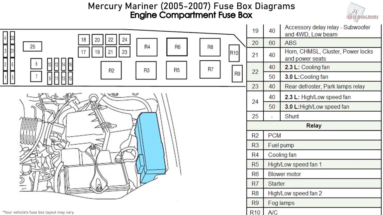
The 2005 Mercury Mariner, a compact SUV sharing its platform with the Ford Escape, utilizes a complex electrical system reliant on fuses and relays for protection and control. Understanding the fuse box diagram is crucial for diagnosing electrical issues, performing modifications, or simply maintaining your vehicle. This article provides a detailed explanation of the 2005 Mercury Mariner fuse box diagram, catering to experienced DIYers.
Purpose of the Fuse Box Diagram
The fuse box diagram serves as a roadmap to your Mariner's electrical system. It's essential for several reasons:
- Troubleshooting Electrical Problems: When a circuit malfunctions (e.g., a non-functioning power window, a blown headlight), the diagram helps you quickly locate the corresponding fuse or relay, allowing for targeted diagnosis and replacement.
- Performing Modifications: If you're adding aftermarket accessories (e.g., a new stereo, auxiliary lighting), understanding the fuse box layout helps you tap into the appropriate circuits safely and reliably. Knowing the amp rating of existing circuits prevents overloading and potential damage.
- General Maintenance and Understanding: Familiarizing yourself with the fuse box diagram provides a better understanding of your vehicle's electrical architecture. You'll learn which circuits control which components, which allows for smarter vehicle ownership and pro-active maintenance.
Key Specs and Main Parts
The 2005 Mercury Mariner typically has two primary fuse box locations:
- Passenger Compartment Fuse Panel: Located underneath the dashboard on the driver's side. This panel primarily houses fuses and relays for interior components such as the radio, power windows, interior lighting, and various control modules.
- Power Distribution Box (Under the Hood): Situated in the engine compartment, this box contains fuses and relays responsible for high-current components like the starter motor, headlights, fuel pump, and ABS system. This box is sometimes called the Battery Junction Box (BJB).
Within each fuse box, you'll find several key components:
- Fuses: Fuses are safety devices designed to protect electrical circuits from overcurrent. They contain a thin wire that melts and breaks the circuit when the current exceeds a pre-determined limit. Fuses are rated in amperes (amps), indicating the maximum current they can safely handle. Common amperage ratings include 5A, 7.5A, 10A, 15A, 20A, 25A, 30A, and higher.
- Relays: Relays are electromechanical switches that use a small control current to switch a larger current. They are used to control high-current devices with a low-current signal from a switch or control module. Relays consist of a coil, contacts (normally open or normally closed), and an armature.
- Circuit Breakers: Some circuits may be protected by circuit breakers. Unlike fuses, circuit breakers can be reset after tripping due to an overcurrent condition.
- Diode: A diode is a two-terminal electronic component that conducts primarily in one direction (asymmetric conductance); it has low (ideally zero) resistance in one direction, and high (ideally infinite) resistance in the other.
- Fuse Puller: A small plastic tool (often integrated into the fuse box cover) used to safely remove fuses. Using pliers can damage the fuse box and the fuse itself.
Understanding Fuse Box Diagram Symbols
Fuse box diagrams use a variety of symbols to represent different components and their functions. Here's a breakdown of common symbols:
- Fuses: Typically represented by a rectangle with a squiggly line inside. The amperage rating is usually printed next to the symbol (e.g., "15A").
- Relays: Usually shown as a square or rectangle with coil and contact symbols inside. The diagram might indicate whether the relay is normally open (NO) or normally closed (NC).
- Wiring: Solid lines represent wires connecting components. Dashed lines may indicate a shielded wire or a ground connection.
- Ground: The ground symbol resembles an inverted pyramid, often filled in.
- Component Icons: Small icons may depict the component protected by the fuse or controlled by the relay (e.g., a lightbulb for headlights, a speaker for the audio system).
Color coding is also used:
- Fuse Color: The color of a fuse corresponds to its amperage rating. Standard color codes (e.g., yellow for 20A, blue for 15A) help you quickly identify the correct fuse.
- Wiring Color: Wire colors are often indicated on the diagram using abbreviations (e.g., "BLU" for blue, "GRN" for green). This helps trace wires and identify potential short circuits.
How It Works
The fuse box is essentially a distribution point for electrical power. Power from the battery is fed into the fuse box, and then distributed to various circuits throughout the vehicle. Each circuit is protected by a fuse of the appropriate amperage rating.
When a circuit experiences an overcurrent (e.g., due to a short circuit or a faulty component), the fuse wire melts, interrupting the flow of current and preventing damage to the wiring and other components. Relays allow low-current switches to control high-current devices. For example, the headlight switch sends a low-current signal to the headlight relay, which then switches on the high-current circuit that powers the headlights.
Real-World Use: Basic Troubleshooting Tips
Here's a basic troubleshooting scenario:
Problem: Your 2005 Mercury Mariner's radio isn't working.
- Consult the Fuse Box Diagram: Locate the fuse box diagram (usually found in the owner's manual or inside the fuse box cover).
- Identify the Radio Fuse: Find the fuse labeled "Radio" or "Audio System" on the diagram. Note its location and amperage rating.
- Inspect the Fuse: Use a fuse puller to remove the fuse. Visually inspect it for a broken filament. If the filament is broken, the fuse is blown.
- Replace the Fuse: Replace the blown fuse with a new fuse of the same amperage rating. Using a fuse with a higher amperage rating can damage the circuit.
- Test: Turn on the radio to see if it now works.
- If the Fuse Blows Again: If the new fuse immediately blows, there's likely a short circuit in the radio wiring or a faulty component in the radio itself. Further diagnosis by a qualified technician is recommended.
Safety Considerations
Working with electrical systems can be dangerous. Here are some important safety precautions:
- Disconnect the Battery: Before working on any electrical circuits, disconnect the negative (-) battery cable to prevent accidental shorts and electrical shock.
- Use the Correct Fuse: Always replace a blown fuse with a fuse of the same amperage rating. Using a higher-rated fuse can overload the circuit and cause a fire.
- Avoid Wet Conditions: Do not work on electrical systems in wet conditions. Water conducts electricity and can create a shock hazard.
- High-Current Components: Be especially cautious when working with high-current components like the starter motor and alternator. These components can deliver a powerful electrical shock.
- Consult a Professional: If you're not comfortable working on electrical systems, consult a qualified mechanic.
Understanding the 2005 Mercury Mariner fuse box diagram is a valuable skill for any DIYer. By using this guide and exercising caution, you can effectively troubleshoot electrical issues, perform modifications, and maintain your vehicle's electrical system.
For your convenience, we have a high-resolution PDF of the 2005 Mercury Mariner fuse box diagram available for download. This diagram includes detailed information about fuse locations, amperage ratings, and circuit descriptions. Having this resource readily available will greatly assist you in your automotive maintenance and repair endeavors.