2005 Nissan Altima Fuse Box Diagram
The 2005 Nissan Altima, like all modern vehicles, relies heavily on a complex electrical system. At the heart of this system lie the fuse boxes, acting as the gatekeepers protecting sensitive components from overcurrent and potential damage. Understanding the fuse box diagram for your 2005 Altima is invaluable for diagnosing electrical issues, performing modifications, and ensuring the overall health and longevity of your vehicle's electrical systems. This article provides an in-depth look at the 2005 Altima fuse box diagram, demystifying its components and empowering you to confidently tackle electrical troubleshooting and repairs.
Purpose of the Fuse Box Diagram
The fuse box diagram serves several crucial purposes:
- Troubleshooting Electrical Problems: When an electrical component malfunctions, the first step is often to check the corresponding fuse. The diagram allows you to quickly identify the correct fuse associated with the faulty system.
- Performing Modifications: Adding aftermarket accessories like lights, audio systems, or alarms requires tapping into the vehicle's electrical system. The diagram helps you locate appropriate power sources and protect new circuits with properly sized fuses.
- Understanding Vehicle Electrical Architecture: Studying the diagram provides insight into how different electrical systems are interconnected and powered, enhancing your overall understanding of your Altima's electrical infrastructure.
- Preventing Damage: Replacing a blown fuse with one of the correct amperage prevents further damage to sensitive electronic components. Using a fuse with a higher amperage rating than specified can lead to overheating and potential fire hazards.
Key Specs and Main Parts
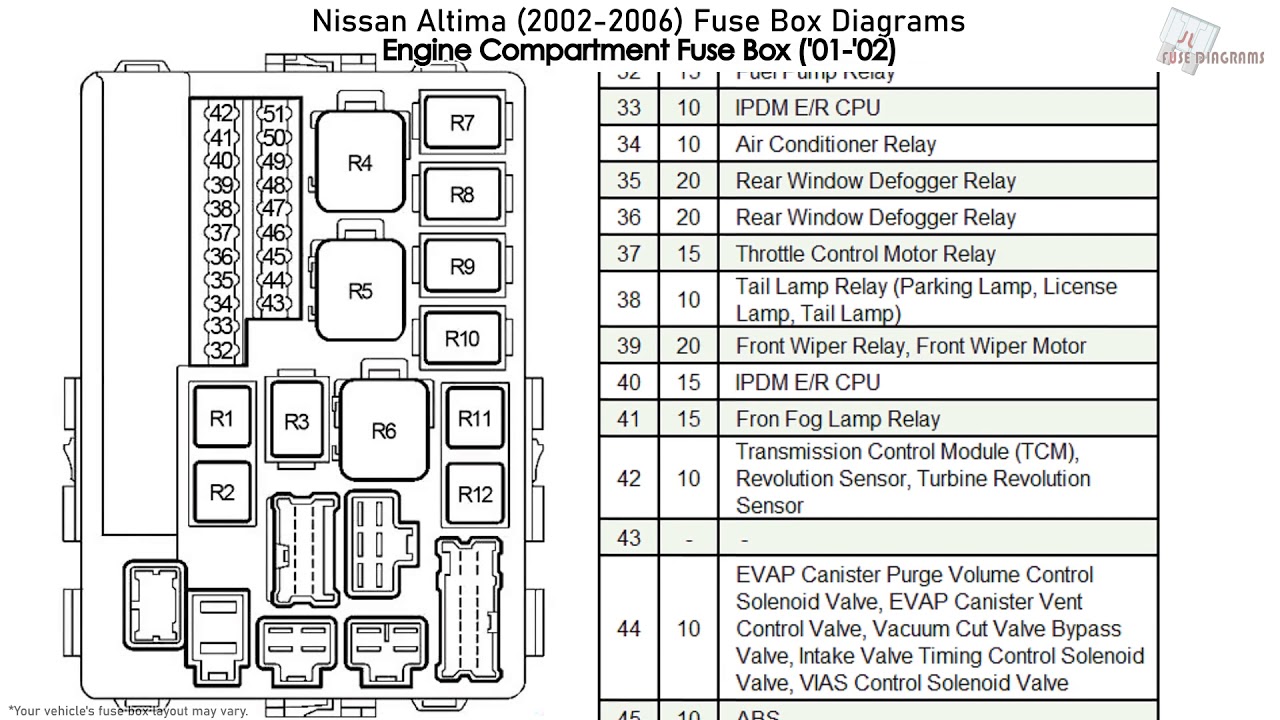
The 2005 Nissan Altima typically has two primary fuse boxes: one located inside the passenger compartment (usually under the dashboard on the driver's side) and another in the engine compartment near the battery. Here's a breakdown of the key components and specifications:
- Fuses: These are the sacrificial components that break the circuit when an overcurrent situation occurs. Fuses are rated in amperes (amps or A), indicating the maximum current they can handle before blowing. Common amperage ratings include 5A, 7.5A, 10A, 15A, 20A, 25A, and 30A.
- Relays: Relays are electromechanical switches that control high-current circuits using a low-current signal. They are used to power components like headlights, the fuel pump, and the starter motor. The fuse box diagram also identifies the location of relays and their corresponding functions.
- Fuse Puller: A small plastic tool included in many fuse boxes, used to safely remove and replace fuses without damaging them or the fuse box terminals.
- Fuse Box Housing: The plastic enclosure that houses the fuses and relays, providing protection and organization.
- Fuse Box Cover: The cover typically has a diagram printed on the inside, illustrating the location and function of each fuse and relay.
Symbols – Lines, Colors, and Icons
Understanding the symbols used in the fuse box diagram is crucial for accurate interpretation. While specific diagrams might have slight variations, the following are common conventions:
- Solid Lines: Indicate a direct electrical connection between components.
- Dotted Lines: May represent ground connections or less critical circuit pathways.
- Colors: While not always present on the diagram itself, wire colors are critical when tracing circuits. A separate wiring diagram (also available for download) details the color coding of each wire. Common colors include Red (power), Black (ground), Blue, Yellow, Green, and White.
- Icons: Icons represent the function of each fuse or relay. These can vary, but some common examples include:
- Headlight Symbol: Fuse for the headlights.
- Horn Symbol: Fuse for the horn.
- Radio Symbol: Fuse for the radio.
- Cigarette Lighter Symbol: Fuse for the cigarette lighter or accessory power outlet.
- Engine Symbol: Fuses related to engine management systems.
- Fan Symbol: Fuses related to cooling fans.
The legend on the fuse box cover or within the service manual is essential for correctly interpreting these symbols.
How It Works
The fuse box works as a central distribution and protection point for the vehicle's electrical system. Power from the battery is distributed through the fuse boxes to various circuits. Each circuit is protected by a fuse of the appropriate amperage rating. If a short circuit or overcurrent occurs in a particular circuit, the fuse "blows," breaking the circuit and preventing damage to the protected components. The relay allows a small current control switch to safely operate larger components, therefore isolating the driver controls from the higher currents.
Real-World Use – Basic Troubleshooting Tips
Here are some practical troubleshooting tips using the fuse box diagram:
- Identify the Problem: Determine which electrical component is malfunctioning.
- Locate the Corresponding Fuse: Using the fuse box diagram, find the fuse associated with the problematic component. Double-check the diagram in your owner’s manual, as sometimes there are minor model-year variations.
- Inspect the Fuse: Visually inspect the fuse. A blown fuse will typically have a broken filament visible through the clear plastic housing.
- Test the Fuse: Use a multimeter set to continuity mode to test the fuse. A good fuse will show continuity (a beep or a low resistance reading), while a blown fuse will show no continuity (an open circuit).
- Replace the Fuse: If the fuse is blown, replace it with a new fuse of the exact same amperage rating. Never use a fuse with a higher amperage rating.
- Test the Component: After replacing the fuse, test the component to see if the problem is resolved.
- If the Fuse Blows Again: If the new fuse blows immediately or shortly after replacement, it indicates a persistent short circuit or overcurrent condition in the circuit. Further diagnosis is required to identify and repair the underlying problem. This might involve checking wiring for damage or shorts to ground.
Safety – Highlight Risky Components
Working with automotive electrical systems involves inherent risks. Here are some critical safety precautions:
- Disconnect the Battery: Before working on the fuse box or any electrical component, disconnect the negative terminal of the battery. This prevents accidental short circuits and electrical shocks.
- Use Insulated Tools: Use tools with insulated handles to minimize the risk of electrical shock.
- Never Bypass a Fuse: Never bypass a fuse by using a wire or other conductive material. This can cause serious damage to the electrical system and create a fire hazard.
- Be Aware of High-Current Circuits: Components like the starter motor and alternator operate on high-current circuits. Exercise extreme caution when working on these systems. The starter circuit and the alternator circuit are typically protected by fusible links, which are larger, more robust fuses designed to handle higher currents, which are typically close to the battery.
- Consult a Professional: If you are uncomfortable working with electrical systems or if you encounter complex problems, consult a qualified automotive electrician.
- Avoid Water: Ensure the fuse box and surrounding area are dry before working on them. Water can conduct electricity and create a shock hazard.
This article provides a detailed overview of the 2005 Nissan Altima fuse box diagram. For your convenience, we have a downloadable PDF file containing the complete diagram. This resource will be invaluable for your troubleshooting and repair endeavors. Remember to prioritize safety and consult a professional if you encounter any uncertainties.