2005 Nissan Altima Fuse Box Diagram Manual
Alright, let's dive into the often-overlooked but incredibly important world of the 2005 Nissan Altima's fuse box diagram. If you're a DIY enthusiast, a budding mechanic, or simply want to better understand your car's electrical system, this guide is for you. We'll break down the diagram, its purpose, its components, and how to use it effectively.
Purpose of the Fuse Box Diagram
Why bother with a fuse box diagram? Well, its main purpose is rapidly identifying and locating fuses and relays within the car's electrical system. This is crucial for:
- Troubleshooting Electrical Problems: When a circuit fails (lights, radio, power windows, etc.), a blown fuse is often the culprit. The diagram allows you to pinpoint the correct fuse to inspect without guessing.
- Performing Electrical Repairs: Understanding the fuse layout is essential for safely working on any electrical component. You need to be able to isolate circuits before disconnecting or reconnecting anything.
- Installing Aftermarket Accessories: Adding a new stereo, alarm system, or other electronic device requires tapping into the car's power. Knowing the fuse box layout lets you safely connect to the appropriate circuits and add an inline fuse for protection.
- General Understanding of Your Vehicle: The diagram is a roadmap to your car's electrical arteries. Studying it improves your overall understanding of how everything is wired.
Key Specs and Main Parts
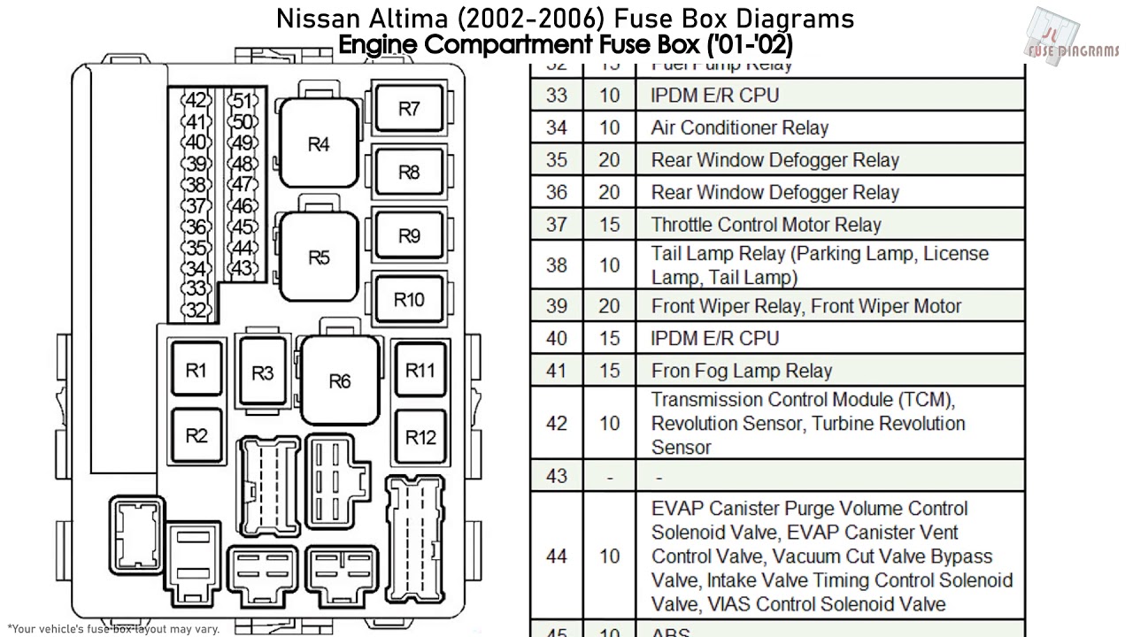
The 2005 Altima typically has two fuse boxes: one located in the cabin, often under the dashboard on the driver's side (the interior fuse box), and another in the engine compartment, usually near the battery or on the fender well (the engine compartment fuse box).
Each fuse box contains:
- Fuses: These are the sacrificial links in the circuits. They are designed to melt and break the circuit if the current exceeds a safe level, preventing damage to other components. Fuses are rated in Amperes (Amps or A), which indicates the maximum current they can handle.
- Relays: Relays are electromechanical switches that allow a low-current circuit to control a high-current circuit. They are used for components like headlights, the fuel pump, and the starter motor, where directly switching the high current through a small switch would be impractical and dangerous.
- Fuse Puller: A small plastic tool included in the fuse box to remove fuses safely.
- Spare Fuses: Usually, there are a few spare fuses of different amperages available in the fuse box.
- The Diagram Itself: A printed or labeled illustration showing the location and function of each fuse and relay. This is the most vital component.
Understanding the Symbols and Layout
The fuse box diagram isn't just a random arrangement of squares and rectangles. It uses standardized symbols and conventions. Here's a breakdown:
- Fuse Representation: Fuses are typically represented as rectangles or squares, often with the amperage rating printed on or near them (e.g., "10A," "15A").
- Relay Representation: Relays are usually depicted as squares or rectangles with internal wiring diagrams showing the coil and contact connections.
- Line Markings: Solid lines on the diagram show the connections between fuses, relays, and the components they protect. Dotted lines may indicate ground connections or alternative circuit paths.
- Color Coding (If Present): Some diagrams use color coding to differentiate between different types of circuits or systems. Consult the legend on the diagram itself to understand the color scheme.
- Icons and Labels: The most important part! Each fuse and relay will have a label indicating its function (e.g., "HEAD LPS" for Head Lamps, "IGN COIL" for Ignition Coil, "FUEL PUMP" for Fuel Pump, "A/C COMP" for Air Conditioning Compressor). These labels are usually abbreviated due to space constraints, so familiarity with common automotive abbreviations is helpful.
The physical layout of the fuses and relays in the fuse box should match the layout shown in the diagram. However, slight variations can occur depending on the exact trim level and options of your vehicle. Always double-check the diagram against the actual fuse box.
How It Works: A Simplified Explanation
Imagine the electrical system as a series of pathways (circuits) leading from the battery to various components. Each circuit is protected by a fuse. When everything is normal, electricity flows freely through the fuse and powers the component.
If a short circuit occurs (e.g., a wire rubs against the chassis, creating a direct path to ground), the current flow increases dramatically. This excessive current generates heat within the fuse. The fuse element (a thin wire or strip of metal) is designed to melt at a specific temperature, breaking the circuit and stopping the flow of electricity before it can damage the wiring, components, or even cause a fire. Think of it as an electrical break point or a circuit breaker for automobiles.
Relays, on the other hand, act as remotely controlled switches. A small current is sent to the relay's coil, which creates an electromagnetic field that pulls a set of contacts together, closing the circuit for the higher-current component. This allows a smaller switch (e.g., a headlight switch) to control a much larger current (e.g., the headlights themselves).
Real-World Use: Basic Troubleshooting
Let's say your 2005 Altima's radio suddenly stops working.
- Consult the Diagram: Locate the fuse box diagram (usually inside the fuse box cover or in the owner's manual).
- Identify the Radio Fuse: Find the fuse labeled "RADIO," "AUDIO," or something similar. Note its amperage rating.
- Locate the Fuse in the Fuse Box: Find the corresponding fuse in the fuse box.
- Inspect the Fuse: Use the fuse puller to remove the fuse. Hold it up to the light. A good fuse will have a continuous metal strip inside. A blown fuse will have a broken or melted strip.
- Replace the Fuse: If the fuse is blown, replace it with a new fuse of the same amperage rating. Never use a fuse with a higher amperage rating; this could bypass the circuit protection and lead to damage or fire.
- Test: Turn on the radio to see if the problem is resolved.
If the new fuse blows immediately or soon after replacement, it indicates a persistent short circuit or overload in the radio circuit. Further diagnosis by a qualified mechanic may be necessary.
Safety Considerations
Working with electrical systems can be dangerous. Here are some essential safety precautions:
- Disconnect the Battery: Before working on any electrical component, disconnect the negative (-) terminal of the battery to prevent accidental short circuits.
- Use the Correct Fuse: Always replace a blown fuse with a fuse of the same amperage rating. Using a higher-rated fuse can overload the circuit and cause damage or fire.
- Avoid Wet Conditions: Never work on electrical systems in wet conditions.
- Identify Risky Components: Be particularly careful around the Airbag system and the ABS system. Improper handling can lead to deployment or malfunction. Refer to the service manual for specific safety procedures before working on these systems.
- If in Doubt, Seek Professional Help: If you're unsure about any aspect of the electrical system, consult a qualified mechanic.
The fuse box diagram is an invaluable tool for maintaining and repairing your 2005 Nissan Altima. By understanding its purpose, components, and symbols, you can confidently tackle many common electrical problems and gain a deeper understanding of your vehicle.
We have the complete 2005 Nissan Altima fuse box diagram file available for download. This detailed diagram will provide you with the exact locations and functions of all fuses and relays in your vehicle. Download it now and keep it handy for future reference. It will save you time and money when troubleshooting electrical issues.