2005 Nissan Altima Radio Wiring Diagram
So, you're tackling some electrical work on your 2005 Nissan Altima's radio system, huh? Smart move! Understanding the wiring diagram is absolutely crucial for anything from a simple speaker upgrade to troubleshooting a complete system failure. This guide will break down the 2005 Altima radio wiring diagram, giving you the knowledge to confidently tackle your project. We’re assuming you have some basic electrical experience – remember to always disconnect the battery before working on any electrical system!
Purpose of the 2005 Altima Radio Wiring Diagram
Why bother with a wiring diagram? Simple. It's your roadmap. Imagine trying to navigate a foreign city without a map – that's what working on car electronics without a diagram is like. Specifically, the 2005 Altima radio wiring diagram serves several key purposes:
- Troubleshooting: Pinpointing the source of electrical problems (like a dead radio or intermittent speaker issues) becomes much easier when you can trace circuits.
- Upgrading: Installing aftermarket stereos, amplifiers, or speakers requires knowing which wires do what. You’ll need to tap into the correct power, ground, and signal wires.
- Repairing: If a wire is cut or damaged, the diagram shows you where it needs to be reconnected.
- Learning: Understanding the diagram helps you grasp the overall architecture of the car's audio system.
Key Specs and Main Parts of the 2005 Altima Radio Wiring
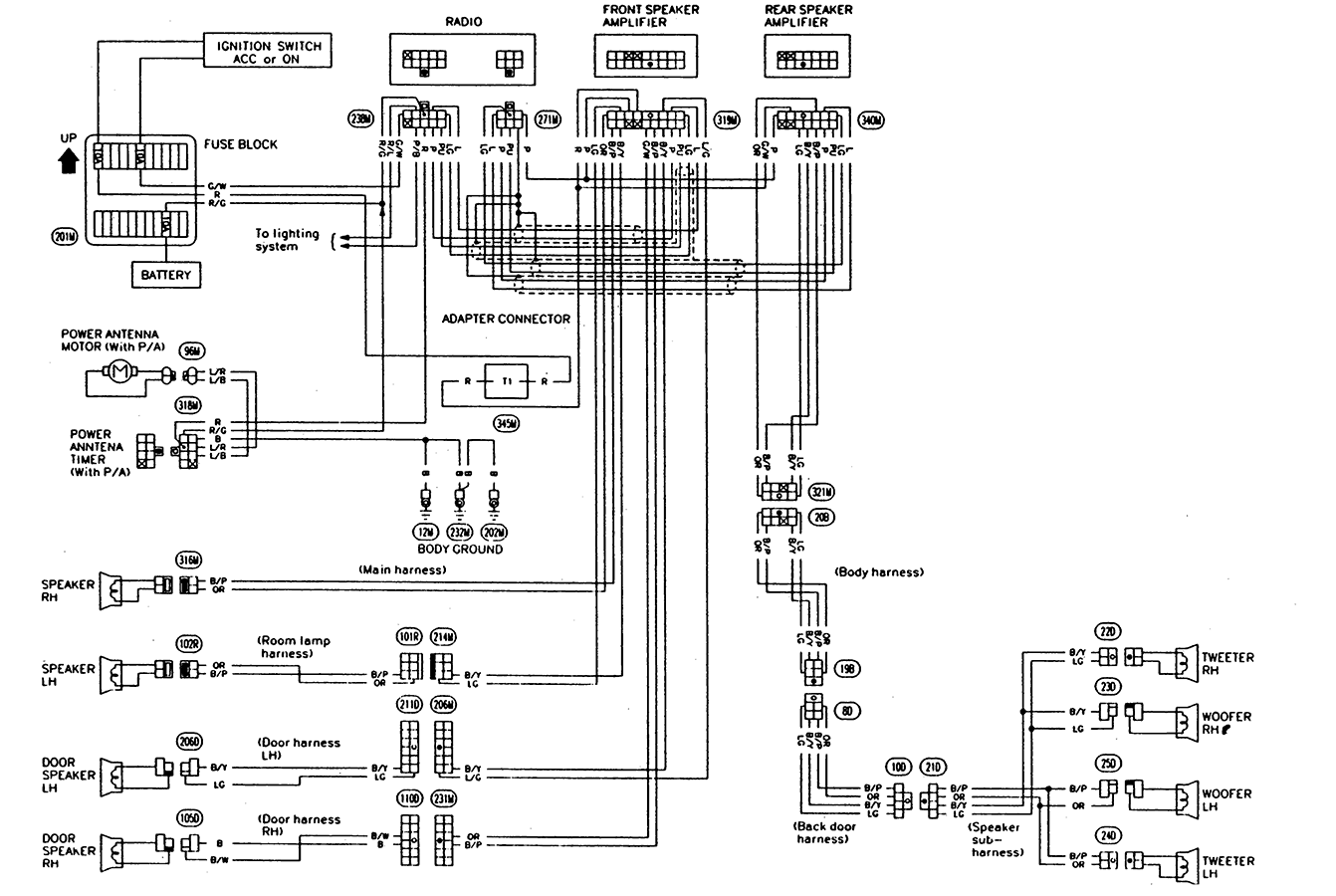
Before we dive into the symbolism, let's identify the main components typically found on a 2005 Altima radio wiring diagram and their key specifications. Keep in mind that slight variations might exist based on trim level (e.g., Bose sound system):
- Head Unit (Radio): The central control unit. It contains the receiver, amplifier, and often a CD player. Key specs include its output wattage (e.g., 20W per channel), impedance (usually 4 ohms), and input voltage (12V DC).
- Speakers: Responsible for converting electrical signals into sound. They are typically 4 ohms impedance. The Altima usually has front door speakers, rear deck or door speakers, and potentially tweeters in the A-pillars.
- Amplifier (if equipped): Found in systems with upgraded sound (like the Bose system). It boosts the signal from the head unit to the speakers. The amplifier will have its own power, ground, input, and output wires.
- Antenna: Receives radio signals. It's usually a single wire connecting to the head unit.
- Wiring Harness: A connector block that plugs into the back of the radio. This is where all the individual wires converge. Understanding the pinout (the arrangement of the wires in the harness) is crucial.
- Power Source: The car's battery provides the power. Fuses protect the radio circuit from overcurrent. Look for a fuse rating (e.g., 10A or 15A) dedicated to the audio system.
- Ground: Provides a return path for the electrical current. Ground wires are usually connected to the car's chassis. A good, clean ground connection is vital for proper operation.
Understanding the Symbols and Conventions
Wiring diagrams aren't written in plain English; they use symbols. Here's a breakdown of the common symbols you'll encounter on a 2005 Altima radio wiring diagram:
- Lines: Lines represent wires. Thicker lines often indicate higher current-carrying capacity (e.g., power wires). Dashed lines may indicate shielded wires or connections that aren't always present.
- Colors: Each wire has a specific color code (e.g., Blue/White, Green/Black). These codes are critical for identifying the wires in your car. Always double-check the color code before making any connections.
- Ground Symbol: Often depicted as three downward-pointing lines, sometimes resembling a triangle. This indicates the wire is connected to the chassis for grounding.
- Fuse Symbol: Looks like a squiggly line inside a rectangle. Indicates the location of a fuse in the circuit.
- Connector Symbols: Represent the wiring harness connectors. They are often numbered or lettered to help you identify the corresponding pins.
- Component Symbols: Resistors, capacitors, diodes, and other electronic components have their own unique symbols. While you likely won't need to understand all of them for basic radio work, it's good to be aware of them.
Color codes are extremely important. Nissan usually follows a standard color coding system, but it's always best to verify the color against the diagram. For example, a Blue/White wire might indicate the remote turn-on for an amplifier.
How It Works: The Radio Circuit Explained
Let's trace the basic flow of electricity in the radio circuit:
- Power: The 12V DC power from the battery flows through a fuse (for protection) to the radio. There are typically two power wires: one for constant power (to retain memory settings) and one for switched power (activated when the ignition is turned on).
- Ground: The radio needs a ground connection to complete the circuit. This is usually a wire connected to the car's chassis.
- Signal Input: The antenna receives radio signals. These signals are fed into the head unit. Additionally, if you're using an auxiliary input (AUX), that is also a signal input.
- Processing: The head unit processes the radio signal, amplifies it (or passes it through to an external amplifier), and sends it to the speakers.
- Signal Output: Speaker wires carry the amplified audio signal from the head unit (or amplifier) to the speakers. There are usually separate positive (+) and negative (-) wires for each speaker.
Think of it like a water pipe system: the battery is the water source, the wires are the pipes, the radio is the processing plant, and the speakers are the sprinklers that output the final product.
Real-World Use: Basic Troubleshooting Tips
Okay, so you have the diagram. How do you use it to fix a problem? Here are a few basic troubleshooting tips:
- No Power to the Radio: Check the fuse first! Use a multimeter to test the fuse for continuity. If the fuse is blown, replace it with one of the same amperage. If it keeps blowing, there's a short circuit somewhere.
- One Speaker Not Working: Swap the speaker with a known good speaker to rule out a bad speaker. If the problem persists, use the wiring diagram to trace the speaker wires back to the head unit (or amplifier). Check for loose connections or damaged wires. Use a multimeter to check for voltage at the speaker terminals when the radio is playing.
- Static or Distortion: Check the antenna connection. Make sure the antenna wire is securely connected to the head unit. Also, check the ground connection for the radio and amplifier. A poor ground can cause noise.
- Radio Turns On But No Sound: Make sure the volume is turned up! Seriously, it happens. Then, check the speaker connections and the output of the amplifier (if equipped).
Remember to always use a multimeter to test for voltage and continuity. A test light can also be useful for checking for power, but a multimeter provides more detailed information.
Safety: Identifying Risky Components
Working with car electronics can be dangerous if you're not careful. Here are a few things to keep in mind:
- Battery: Always disconnect the negative terminal of the battery before working on any electrical system. This prevents accidental shorts and electrical shocks.
- Airbags: Be extremely careful when working near airbags. Accidental deployment can cause serious injury. It's generally best to avoid working on airbag-related wiring unless you're specifically trained to do so. Consult the service manual for specific precautions related to disabling and enabling the airbag system.
- Wiring: Never cut or splice wires without knowing what they do. Use the wiring diagram to identify the wires before making any modifications.
- Short Circuits: Be aware of the potential for short circuits. If you accidentally touch a live wire to ground, you could damage the radio or other components. Always use insulated tools and work carefully.
- High Current Wires: Pay close attention to the gauge of the wires. Thicker wires carry more current. Don't try to tap into a high-current wire with a smaller gauge wire, as this could create a fire hazard.
Important Note: Working with car electronics involves risk. If you're not comfortable with electrical work, it's best to take your car to a qualified mechanic. Incorrect wiring can damage your car's electrical system and even create a fire hazard.
With the right knowledge and precautions, you can successfully troubleshoot and upgrade your 2005 Nissan Altima's radio system. Remember to take your time, double-check your work, and consult the wiring diagram whenever you're unsure about something.
We have access to the complete 2005 Nissan Altima radio wiring diagram. Please note that while we can share the diagram, interpreting it and safely applying its information to your vehicle is your responsibility. We strongly encourage thorough research and caution before undertaking any electrical work.