2005 Nissan Maxima Fuse Box Diagram
Okay, let's dive into the fuse box diagram for the 2005 Nissan Maxima. Knowing how to read and understand this diagram is crucial whether you're tackling a minor electrical issue, adding aftermarket accessories, or simply trying to better understand your car's electrical system. Think of it as the roadmap to your Maxima's nervous system.
Purpose: Your Electrical Troubleshooting Guide
Why bother with a fuse box diagram? The primary reason is for troubleshooting. If something electrical isn't working – a taillight, your radio, even the engine starting – checking the fuses is one of the first steps. The diagram tells you exactly which fuse controls which circuit, saving you tons of time and frustration. It also helps prevent misdiagnosis, which can lead to unnecessary part replacements and even more problems down the line.
Beyond troubleshooting, the diagram is invaluable for installing aftermarket accessories. Want to wire up a new stereo, auxiliary lighting, or a dashcam? You'll need to tap into the electrical system. The diagram helps you identify safe and appropriate circuits to tap into, avoiding overload and potential damage to your car's electrical system. Understanding the diagram also provides a foundation for learning about automotive electrical systems in general.
Key Specs and Main Parts of the 2005 Maxima Fuse System
The 2005 Maxima, like most modern cars, has multiple fuse boxes. The two most important are:
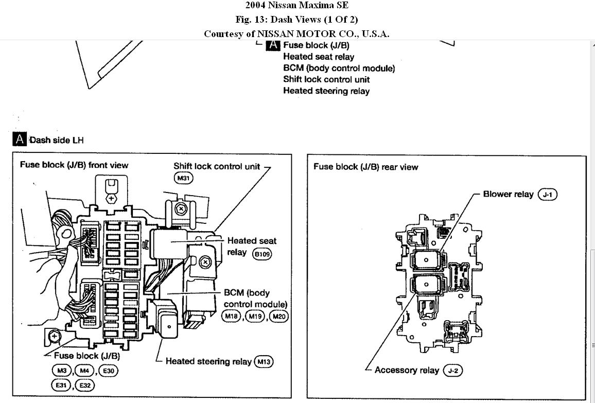
- The Interior Fuse Box: Typically located under the dashboard, usually on the driver's side near the steering column or behind a small access panel. This box primarily handles circuits related to interior components like the radio, lights, power windows, and accessories.
- The Engine Compartment Fuse Box: Situated under the hood, usually near the battery. This box protects circuits vital for engine operation, such as the fuel pump, ignition system, cooling fan, and headlights.
Within each fuse box, you'll find:
- Fuses: These are the sacrificial links in the circuit. They're designed to blow (open) if the current exceeds a safe level, protecting the wiring and components downstream. Fuses are rated in amperes (amps or A), indicating the maximum current they can handle before blowing. Common fuse ratings in the Maxima are 5A, 7.5A, 10A, 15A, 20A, 25A, and 30A.
- Relays: These are electrically operated switches that control high-current circuits using a low-current control signal. For example, the starter relay allows a small signal from the ignition switch to activate the high-current circuit that cranks the engine.
- The Fuse Box Housing: This plastic enclosure provides a safe and organized location for the fuses and relays. It often includes a legend (the diagram) indicating the function of each fuse and relay.
- Test Points (sometimes): Some fuse boxes have test points that allow you to easily check for voltage at a specific fuse location without removing the fuse.
The 2005 Maxima typically uses blade-type fuses, also known as spade fuses or plug-in fuses. These come in various sizes (ATO, Mini, Micro2) but the Maxima predominantly uses ATO and Mini fuses.
Decoding the Diagram: Symbols, Lines, and Colors
The fuse box diagram isn't just a random collection of lines and numbers. It's a standardized representation of the electrical circuits within the fuse box. Here's what you need to know:
- Fuse Symbols: The standard symbol for a fuse is a wavy line inside a rectangle. Older diagrams might use a simple line.
- Relay Symbols: Relays are typically represented by a square or rectangle containing a coil symbol and a switch symbol. The coil represents the electromagnet that activates the switch.
- Lines: Lines represent wires connecting the fuses and relays to various components. A thicker line might indicate a heavier gauge wire, capable of carrying more current.
- Numbers: Each fuse and relay location is assigned a number. This number corresponds to an entry in the legend, which tells you the function of that fuse or relay.
- Colors (on some diagrams): Some diagrams use colors to differentiate between different types of circuits. For example, red might indicate a constant power source, while blue might indicate an ignition-switched power source. However, color-coding is not universally used, so always refer to the legend.
- Abbreviations: The diagram and legend will use abbreviations to save space. Common abbreviations include:
- ACC: Accessory
- IGN: Ignition
- ENG: Engine
- A/C: Air Conditioning
- HTR: Heater
- RR: Rear
- LH: Left Hand
- RH: Right Hand
Understanding the Legend is Key! The legend is the most crucial part of the diagram. It provides a detailed description of the function of each fuse and relay, including the amperage rating of the fuse. Without the legend, the diagram is practically useless.
How It Works: From Battery to Component
The fuse box acts as a central distribution point for electrical power. Power from the battery flows through the main power wire to the fuse boxes. From there, it's distributed to various circuits, each protected by a fuse. If a fault occurs in a circuit (e.g., a short to ground), the current will spike, causing the fuse to blow. This breaks the circuit and prevents damage to the wiring and components connected to that circuit. Relays, on the other hand, allow a low-current signal to control a high-current circuit. This is important for safety and efficiency, as it allows switches and control modules to operate high-power devices without handling the full current load.
Real-World Use: Basic Troubleshooting Tips
Here's a basic troubleshooting scenario:
- Identify the Problem: Determine which electrical component is not working.
- Consult the Diagram: Locate the fuse or relay associated with that component in the fuse box diagram.
- Inspect the Fuse: Remove the fuse and visually inspect it. If the wire inside the fuse is broken or blackened, the fuse is blown.
- Test the Fuse (optional): Use a multimeter to test the fuse for continuity. A blown fuse will show no continuity.
- Replace the Fuse: Replace the blown fuse with a new fuse of the same amperage rating. Never use a fuse with a higher amperage rating, as this could damage the wiring.
- Test the Component: After replacing the fuse, test the component to see if it is working again.
- If the Fuse Blows Again: If the new fuse blows immediately or shortly after being replaced, there is likely a short circuit in the wiring or the component itself. This requires further investigation by a qualified mechanic.
Safety: Handling Risky Components
Working with automotive electrical systems can be dangerous if you're not careful. Here are some important safety precautions:
- Disconnect the Battery: Always disconnect the negative battery cable before working on the electrical system. This prevents accidental shorts and electrical shocks.
- Avoid Tampering with Airbag Circuits: The airbag system is highly sensitive and can be accidentally deployed if tampered with. Airbag circuits are often colored bright yellow and should be avoided unless you have specific training and expertise.
- Do Not Exceed Fuse Ratings: Never replace a fuse with a higher amperage rating. This can overload the wiring and cause a fire.
- Use Proper Tools: Use insulated tools when working on the electrical system to prevent shocks.
- Work in a Well-Ventilated Area: Some electrical components can emit harmful fumes, so work in a well-ventilated area.
Important Note on High-Current Circuits: Be especially careful when working with high-current circuits, such as the starter motor circuit or the alternator circuit. These circuits can carry a significant amount of current and can cause serious burns or shocks if mishandled.
Remember, if you are unsure about any aspect of working on your car's electrical system, it is always best to consult a qualified mechanic.
This information should give you a solid understanding of your 2005 Nissan Maxima's fuse box diagram. We have the complete and detailed diagram available for download. This document will allow you to zoom in and see every detail clearly. Good luck with your repairs!