2005 Nissan Sentra Fuse Box Diagram
If you own a 2005 Nissan Sentra and are even remotely inclined towards DIY car maintenance, understanding your vehicle's fuse box diagram is absolutely crucial. This isn't just about replacing a blown fuse; it's about understanding your car's electrical system, troubleshooting issues effectively, and even safely undertaking modifications. This article will provide a detailed breakdown of the 2005 Nissan Sentra fuse box diagram, empowering you to tackle electrical repairs and upgrades with confidence.
Purpose of Understanding the Fuse Box Diagram
The fuse box diagram serves several vital purposes:
- Troubleshooting Electrical Problems: Identifying a blown fuse related to a specific circuit (e.g., headlights, radio) is the first step in diagnosing electrical issues. The diagram pinpoint's the exact fuse you need.
- Preventing Further Damage: Replacing a blown fuse with one of the correct amperage prevents potential damage to other components in the circuit. Using the wrong amperage fuse can lead to overheating, melting wires, and even fires.
- Performing Modifications: If you're adding aftermarket accessories like a sound system or auxiliary lighting, you'll need to tap into the vehicle's electrical system. The fuse box diagram will help you identify appropriate circuits to tap into and ensure proper fusing for the new accessory.
- General Understanding of Vehicle Systems: Familiarizing yourself with the fuse box diagram provides a deeper understanding of how your car's electrical system is organized and how different components interact.
Key Specs and Main Parts
The 2005 Nissan Sentra typically has two fuse boxes: one located inside the passenger compartment (usually under the dashboard on the driver's side) and another located under the hood, near the battery. The under-hood fuse box is often referred to as the "engine compartment fuse box" or "primary fuse box."
- Passenger Compartment Fuse Box: This fuse box generally houses fuses for interior components like the radio, interior lights, power windows, and various control modules.
- Engine Compartment Fuse Box: This fuse box contains fuses for engine management systems, headlights, starting system, and other critical engine-related functions. It also typically houses relays.
- Fuses: These are small, color-coded components that protect electrical circuits from overcurrent. They are rated in amperes (A), indicating the amount of current they can handle before blowing. Common amperage ratings include 5A, 7.5A, 10A, 15A, 20A, 25A, and 30A.
- Relays: These are electromechanical switches that allow a low-current circuit to control a high-current circuit. They are commonly used to control headlights, the starter motor, and other high-power devices.
- Fuse Puller: A small plastic tool designed to safely remove fuses from the fuse box without damaging them. Most fuse boxes include a fuse puller attached to the inside of the cover.
Symbols and Diagram Explanation
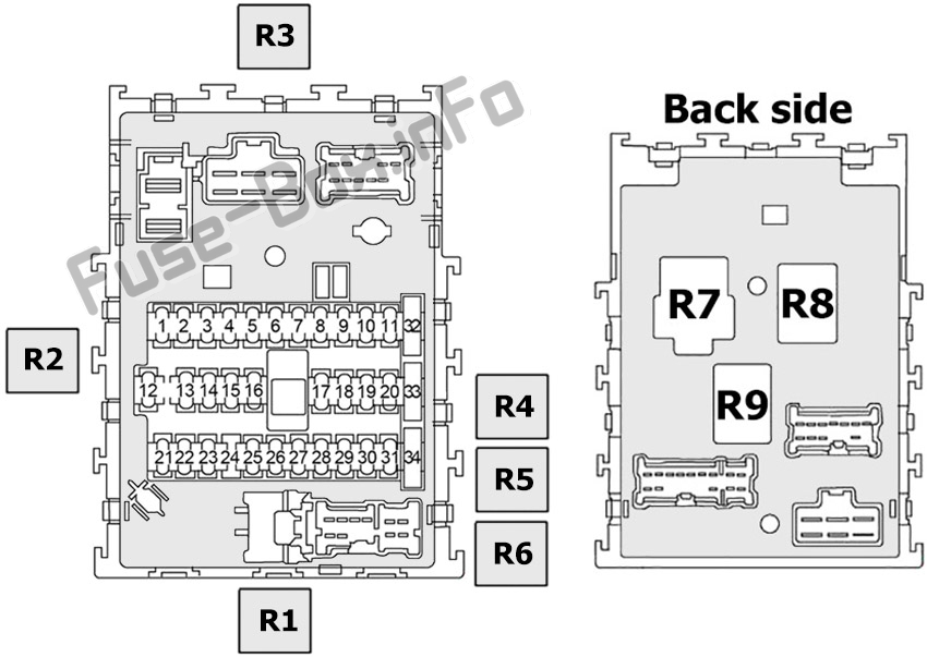
A typical fuse box diagram consists of a grid representing the physical layout of the fuses and relays within the fuse box. Each position is labeled with a number or code corresponding to a specific electrical circuit. The diagram also includes symbols and abbreviations to indicate the function and amperage of each fuse.
- Lines: Lines represent the electrical circuits. A solid line generally means a direct connection, while a dashed line might indicate a connection through a switch or other component.
- Colors: The color of the fuse itself indicates its amperage rating. While not always standardized, there's a common color-coding system:
- Yellow: 20A
- Blue: 15A
- Red: 10A
- Brown: 7.5A
- Orange: 5A
- Icons/Abbreviations: The diagram will use icons or abbreviations to represent the function of each fuse. Common examples include:
- Headlights: Headlamp icon or "HEAD"
- Radio: Speaker icon or "AUDIO"
- Power Windows: Window icon or "PWR WDW"
- Engine Control Module (ECM): "ECM"
- Anti-lock Braking System (ABS): "ABS"
- Air Conditioning (A/C): "A/C"
The diagram will often include a legend explaining the meaning of each symbol and abbreviation. Pay close attention to the legend; it's the key to correctly interpreting the diagram.
How It Works
Fuses are designed as the weakest point in an electrical circuit. When an overcurrent occurs (e.g., due to a short circuit), the fuse's internal filament melts, breaking the circuit and preventing damage to other components. Think of it like a sacrificial lamb. The fuse blows, saving more expensive components from damage.
Relays act as remote switches. A low-current signal energizes the relay's coil, which then closes a set of contacts, allowing a high-current circuit to be completed. This is essential for controlling high-power devices like headlights or the starter motor, where the current draw would be too much for a simple switch in the passenger compartment.
Real-World Use: Basic Troubleshooting Tips
Here's a basic troubleshooting scenario:
- Symptom: Your radio suddenly stops working.
- Step 1: Consult the Fuse Box Diagram: Locate the fuse box diagram (either printed on the inside of the fuse box cover or in your owner's manual).
- Step 2: Identify the Radio Fuse: Find the fuse labeled "RADIO" or "AUDIO" on the diagram. Note its location and amperage rating.
- Step 3: Inspect the Fuse: Using a fuse puller, carefully remove the fuse. Visually inspect it. If the filament inside the fuse is broken, the fuse is blown.
- Step 4: Replace the Fuse: Replace the blown fuse with a new fuse of the exact same amperage rating.
- Step 5: Test: Turn on the radio to see if it now works.
- If the Fuse Blows Again: If the new fuse blows immediately or shortly after being replaced, this indicates a more serious problem in the radio circuit, such as a short circuit. Further diagnostics are required. Do not simply keep replacing fuses with higher amperage ratings, as this can cause serious damage or a fire. You'll likely need to consult a qualified mechanic.
Safety Considerations
Working with electrical systems can be dangerous. Always follow these safety precautions:
- Disconnect the Battery: Before working on any electrical component, disconnect the negative (-) terminal of the battery. This will prevent accidental short circuits and electric shocks.
- Use the Correct Fuse Rating: Never replace a fuse with one of a higher amperage rating. This can overload the circuit and cause a fire.
- Don't Bypass Fuses: Never use a wire or other object to bypass a fuse. This eliminates the circuit protection and can lead to serious damage or a fire.
- Handle Relays Carefully: Relays can be sensitive to static electricity. Avoid touching the pins directly.
- Be Aware of SRS (Airbag) Components: Some fuses and circuits are related to the Supplemental Restraint System (SRS), including airbags. Mishandling these circuits can cause the airbags to deploy accidentally, resulting in injury. If you are unsure, consult a professional.
The engine compartment fuse box typically handles higher amperage fuses and circuits directly connected to the battery. Exercise extra caution when working in this area.
By understanding the 2005 Nissan Sentra fuse box diagram and following proper safety precautions, you can confidently diagnose and repair basic electrical problems, saving time and money. Remember, if you're not comfortable working with electrical systems, it's always best to consult a qualified mechanic.
We have a high-resolution, printable version of the 2005 Nissan Sentra fuse box diagram available for download. This diagram provides a clear and detailed representation of fuse and relay locations, amperages, and circuit functions. This resource is perfect for keeping in your garage or workshop for easy reference. Contact us for access.