2005 Pontiac Grand Prix Radio Wiring Diagram
Alright, let's dive into the wiring diagram for the 2005 Pontiac Grand Prix radio. This document is your best friend when you're tackling anything related to the audio system, from replacing a blown fuse to installing a new head unit or diagnosing speaker issues. It gives you a clear roadmap of how everything connects and interacts.
Purpose and Importance
Why bother with a wiring diagram? Simple: it's the key to understanding and safely modifying or repairing your Grand Prix's audio system. Without it, you're basically groping in the dark, risking damage to your car's electrical system or even personal injury. Whether you're troubleshooting a malfunctioning speaker, adding a subwoofer, or upgrading to a modern head unit, this diagram will guide you every step of the way. Furthermore, studying the diagram is a great way to learn about automotive electrical systems in general.
Key Specs and Main Parts
The 2005 Grand Prix audio system, like most car audio systems, consists of several key components:
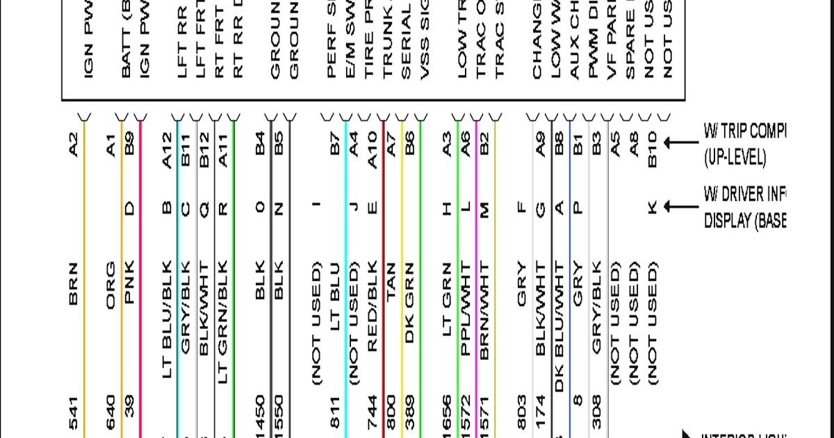
- Head Unit (Radio): This is the brains of the operation – the source of your audio. It includes the AM/FM tuner, CD player (if equipped), and in some cases, connections for auxiliary input (AUX) or even early forms of iPod integration. The wiring diagram will show all the input and output connections, including power, ground, antenna, speaker wires, and any communication lines (like those used for steering wheel controls).
- Speakers: Usually, the Grand Prix will have speakers in the front doors and the rear deck (or doors if it's a sedan). The wiring diagram will indicate the positive (+) and negative (-) connections for each speaker. Incorrect polarity can significantly degrade sound quality.
- Amplifier (If Equipped): Some Grand Prix models came with a factory amplifier. The diagram will show its location, power source, and the connections to the head unit and speakers. Understanding the amplifier wiring is crucial if you're planning to bypass it or upgrade to an aftermarket amplifier.
- Antenna: This receives the radio signal. The diagram shows its connection to the head unit.
- Wiring Harness: The wiring harness bundles all the wires together. The diagram breaks down the harness into individual wires and their destinations.
- Grounding Points: These are critical. They ensure that all components have a common reference point for voltage. A bad ground can cause all sorts of problems, from noise in the audio to complete system failure. The diagram will show the location of the main grounding points related to the audio system.
Understanding the Symbols
Wiring diagrams use a specific set of symbols to represent components and connections. Here's a breakdown of the most common ones you'll encounter in the 2005 Grand Prix radio wiring diagram:
- Lines: Lines represent wires. The thickness of the line might sometimes indicate the gauge (thickness) of the wire, although this is not always consistent.
- Colors: Each wire is identified by a color code (e.g., RED, BLK, WHT/BLU). These color codes are essential for tracing wires in the actual car. Pay very close attention to color codes when making any modifications!
- Circles: Circles with numbers or letters inside often indicate connector pins.
- Rectangles: These generally represent components like the head unit, amplifier, or other electronic modules.
- Ground Symbol: Usually a series of horizontal lines descending to a point, this indicates a ground connection.
- Fuse Symbol: A squiggly line inside a rectangle or other shape represents a fuse. The diagram might also indicate the fuse amperage rating.
The key will specify abbreviations for the wire colors, such as:
- BLK - Black
- RED - Red
- WHT - White
- GRN - Green
- BLU - Blue
- YEL - Yellow
- BRN - Brown
- ORG - Orange
Also keep an eye out for splices represented as a dot where two or more wires connect. This shows wires coming together from different sources.
How It Works: The Audio Signal Path
The 2005 Grand Prix audio system works by sending an audio signal from the head unit to the speakers (possibly through an amplifier). Here's a simplified overview:
- The head unit generates an audio signal, either from the radio tuner, CD player, or an auxiliary input.
- This signal is then sent through the wiring harness to the speakers. If an amplifier is present, the signal first goes to the amplifier's input.
- The amplifier boosts the audio signal's power.
- The amplified signal is then sent to the speakers, causing them to vibrate and produce sound.
- Power is provided from the car's battery to the radio and amplifier. Ground connections are essential for completing the circuit.
The wiring diagram visually represents this flow of information. Tracing the wires from the head unit to the speakers will reveal the entire audio signal path.
Real-World Use: Troubleshooting
The wiring diagram is invaluable for troubleshooting common audio problems. Here are a few examples:
- No Sound: If you have no sound from all speakers, check the power and ground connections to the head unit and amplifier (if equipped). Use the wiring diagram to locate the correct wires and grounding points. Also, check the fuses related to the audio system.
- Sound From Only One Speaker: If only one speaker is working, check the speaker wiring and the speaker itself. Use the wiring diagram to identify the wires connected to that specific speaker. Test the speaker with a multimeter to see if it's blown. Check the speaker wire for continuity between the head unit and speaker.
- Distorted Sound: Distorted sound can be caused by a blown speaker, a bad amplifier, or a grounding issue. Use the wiring diagram to isolate the problem component.
- Radio Doesn't Turn On: Inspect the radio's power source and ground connections. Consult the wiring diagram for the right wires. Use a multimeter to verify voltage and ground at the connector. Check the appropriate fuses as well.
Safety Precautions
Working with car electrical systems can be dangerous. Always disconnect the negative terminal of the battery before working on any electrical components. This will prevent accidental shorts and potential electrocution. Be particularly careful when working around the following:
- Airbag System: The airbag system has its own wiring and control module. Accidentally triggering an airbag can cause serious injury. Avoid working near airbag components unless you're specifically trained and equipped to do so. The radio usually does not intersect with any airbag components.
- High-Current Wires: The main power wires for the head unit and amplifier can carry a significant amount of current. Avoid cutting or splicing these wires while the battery is connected.
- Capacitors: Some amplifiers contain large capacitors that can store a charge even after the power is disconnected. Discharge these capacitors before working on the amplifier. (This is more relevant when disassembling the amplifier itself, not just working with its wiring).
Also, use proper tools and techniques. Don't force anything. If you're unsure about something, consult a qualified mechanic.
Always double-check your work and test the system thoroughly after making any modifications or repairs.
With the 2005 Pontiac Grand Prix radio wiring diagram and a little patience, you'll be well-equipped to tackle most audio-related projects. Remember to work safely, take your time, and double-check your connections. Good luck!
We have a digital copy of the 2005 Pontiac Grand Prix radio wiring diagram available for download. It will be a valuable resource for your projects. Simply request the file to obtain the link.