2005 Silverado Blower Motor Resistor Wiring Diagram
If you're tackling HVAC problems in your 2005 Silverado, understanding the blower motor resistor wiring diagram is crucial. Whether you're troubleshooting a faulty fan speed, planning a custom wiring project, or just expanding your automotive knowledge, this guide will provide a comprehensive overview. We'll break down the diagram, explain its components, and offer practical troubleshooting tips.
Why This Diagram Matters
The blower motor resistor controls the speed of your HVAC blower fan. A malfunctioning resistor can result in the fan only working on certain speeds (usually high), not working at all, or working intermittently. Having access to the wiring diagram allows you to:
- Diagnose Fan Speed Issues: Pinpoint shorts, opens, or incorrect voltages in the blower motor circuit.
- Perform Repairs: Identify the correct wires to splice, test, or replace when dealing with a faulty resistor or related wiring.
- Plan Custom Modifications: Integrate aftermarket components or rewire your HVAC system for specific needs.
- Gain Deeper Understanding: Demystify the electrical workings of your vehicle's climate control system.
Key Specs and Main Parts
Before diving into the diagram itself, let's familiarize ourselves with the key components involved:
- Blower Motor Resistor: This component is a series of resistors, each designed to drop voltage to the blower motor, thereby controlling its speed. It's usually located in the HVAC housing, near the blower motor, to benefit from the airflow for cooling.
- Blower Motor: The electric motor that powers the fan, circulating air through the HVAC system.
- Blower Motor Control Switch (or HVAC Control Module): The switch (or module) on your dashboard that allows you to select the desired fan speed. This switch directs power to the appropriate resistor tap.
- Wiring Harness: The bundle of wires connecting all components of the blower motor circuit.
- Ground Connection: A crucial connection providing a return path for current to the vehicle's chassis, ensuring proper circuit operation.
- Fuse: A safety device designed to protect the circuit from overcurrent. It's usually located in the under-hood or in-cab fuse box.
The 2005 Silverado’s blower motor resistor system typically utilizes 4-5 distinct fan speeds. The exact resistance values of the resistor elements can vary slightly depending on the trim level and options package of your truck.
Understanding the Wiring Diagram: Symbols, Lines, and Colors
A wiring diagram is essentially a roadmap of the electrical circuit. Let's decode the common symbols you'll encounter:
- Solid Lines: Represent wires. Thicker lines may indicate wires carrying higher current.
- Dashed Lines: Often indicate a wire shield, a ground connection, or a connection within a module.
- Circles/Dots: Indicate wire splices or connections. A solid dot typically means a permanent connection, while an open circle might signify a connector.
- Resistor Symbol (Zig-zag Line): Represents the resistors within the blower motor resistor pack.
- Motor Symbol (Circle with "M" inside): Represents the blower motor itself.
- Ground Symbol (Downward Pointing Triangles): Represents a connection to the vehicle's chassis ground.
- Color Codes: Wire colors are usually indicated with abbreviations, such as:
- BK: Black
- RD: Red
- OR: Orange
- YE: Yellow
- GN: Green
- BL: Blue
- WH: White
- Fuse Symbol: A squiggly line between two vertical lines, representing the fuse in the circuit. The amperage rating is typically noted next to the fuse symbol (e.g., 25A).
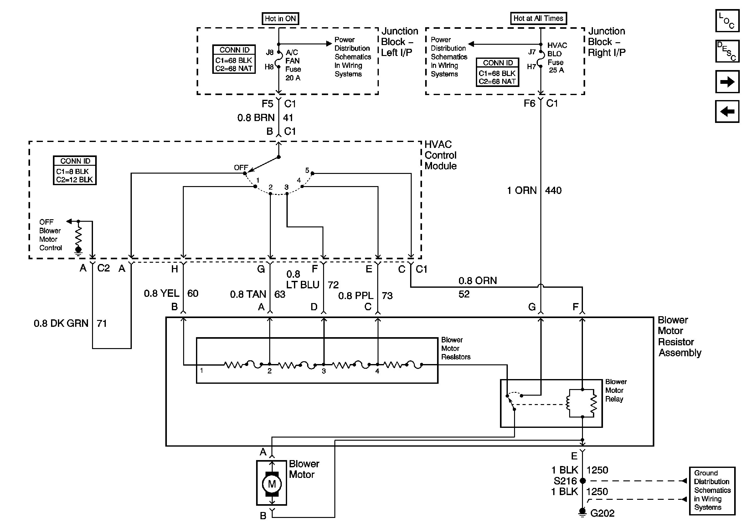
The diagram will typically show the battery positive voltage going to the blower motor circuit, running through the fuse, then to the blower switch. The switch then sends the voltage through the resistor block to the blower motor, then back to ground to complete the circuit.
How It Works: From Switch to Fan
Let's trace the path of electricity through the blower motor circuit:
- Power Source: Battery voltage is fed into the system, protected by a fuse.
- Blower Motor Switch: When you select a fan speed on the dashboard, the switch closes a specific circuit, sending power to one of the resistor taps.
- Blower Motor Resistor: The selected resistor element reduces the voltage going to the blower motor. High speeds bypass the resistor and send full voltage to the motor. Lower speeds use the resistor block.
- Blower Motor: The reduced voltage powers the blower motor, causing it to spin at the selected speed.
- Ground: The current then flows from the blower motor to a grounding point, completing the circuit back to the battery.
The key to understanding the system is that each resistor provides a different level of resistance, directly impacting the voltage supplied to the blower motor. Less resistance = Higher voltage = Higher fan speed.
Real-World Use: Troubleshooting Tips
Here are some common issues and how the wiring diagram can assist in troubleshooting:
- Fan Only Works on High: This is a classic sign of a failed blower motor resistor. The wiring diagram helps you locate the resistor, identify the common wire (usually the one that feeds the resistor block), and test the individual resistor elements for continuity.
Using a multimeter, you can check the resistance across each resistor element. An open circuit (infinite resistance) indicates a failed resistor.
- No Fan Operation at All: Check the fuse first! If the fuse is good, use the diagram to trace voltage from the battery to the blower motor switch, then to the blower motor. If you're not getting voltage at the blower motor, there's a break in the circuit somewhere.
- Fan Works Intermittently: This can be caused by a loose connection, a faulty blower motor switch, or a failing blower motor. The diagram helps you identify all connections and test for voltage drops.
- Burning Smell: Often indicates a short circuit or excessive current draw. Immediately disconnect the battery and use the diagram to locate the source of the short.
Important: Before replacing any components, always double-check the wiring diagram to ensure you're working with the correct wires. Mismatched wires can lead to further damage.
Safety Considerations
Working with electrical components can be dangerous. Here are some safety precautions:
- Disconnect the Battery: Always disconnect the negative battery cable before working on any electrical circuits. This prevents accidental shorts and shocks.
- Handle the Blower Motor Resistor with Care: The resistor can get extremely hot during operation. Allow it to cool down before handling.
- Use a Multimeter Correctly: Ensure your multimeter is set to the correct setting (voltage, resistance, continuity) and that you understand how to interpret the readings.
- Avoid Tampering with Airbag Systems: Airbag wiring is often located near HVAC components. Do not tamper with any yellow-sleeved connectors, as these are part of the airbag system.
The blower motor resistor itself can get very hot, especially if there is a wiring problem or the blower motor is failing. This is because it's dissipating electrical energy as heat. Be careful not to touch the resistor while the system is operating, and allow it to cool before handling.
By understanding the 2005 Silverado blower motor resistor wiring diagram and following these guidelines, you can confidently diagnose and repair HVAC issues, saving time and money while expanding your automotive skillset.
We have a copy of the 2005 Silverado Blower Motor Resistor Wiring Diagram available for download. It provides a more detailed view of the circuit and can be a valuable resource during troubleshooting and repair.