2006 Chevy Silverado Trailer Wiring Diagram
Alright, let's dive into the trailer wiring diagram for a 2006 Chevy Silverado. Understanding this diagram is crucial for anyone looking to install a trailer brake controller, repair faulty trailer lights, diagnose electrical issues, or even customize their truck's towing capabilities. We're talking about a critical system here, so getting it right is paramount for safety and functionality.
Purpose: Why Bother with the Wiring Diagram?
Why spend the time deciphering this seemingly complex web of lines and symbols? Well, think about it: proper trailer wiring is essential for several reasons:
- Safety: Functioning brake lights, turn signals, and running lights on your trailer are non-negotiable for safe towing.
- Legal Compliance: Most jurisdictions require properly functioning trailer lights. A faulty system can result in fines.
- Brake Controller Integration: If you're hauling a heavy trailer, a brake controller is a must-have. The wiring diagram is your roadmap for connecting it correctly.
- Troubleshooting: When your trailer lights act up, the wiring diagram is your best friend for pinpointing the problem.
- Customization: Maybe you want to add backup lights to your trailer or install a 12V power supply. The diagram is your starting point for any modifications.
Key Specs and Main Parts of the 2006 Silverado Trailer Wiring
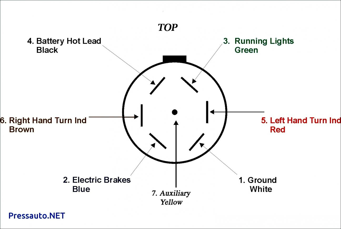
The 2006 Silverado typically uses a 7-way round connector, also known as a 7-way RV blade connector. This is the industry standard for larger trailers. Here's a breakdown of the key components and their functions:
- 7-Way Connector (RV Blade): This is the physical interface between your truck and the trailer. It has seven pins, each carrying a specific electrical signal.
- Ground (White Wire): Provides a common ground for all electrical circuits. Essential for completing the circuits and ensuring proper function.
- Tail/Running Lights (Brown Wire): Powers the taillights and running lights on the trailer.
- Left Turn/Stop Light (Yellow Wire): Controls the left turn signal and brake light on the trailer.
- Right Turn/Stop Light (Green Wire): Controls the right turn signal and brake light on the trailer.
- Electric Brakes (Blue Wire): Connects to the electric brake controller, providing power to the trailer's brakes. This is a variable voltage signal modulated by the brake controller.
- Reverse Lights (Black Wire): Powers the reverse lights on the trailer.
- Auxiliary Power (Red or Orange Wire): Provides a 12V DC power source to the trailer, often used for charging a trailer battery or powering interior lights.
Understanding the *purpose* of each wire is half the battle. Remember, color codes can sometimes vary slightly, but the *function* of each pin remains the same.
Decoding the Symbols: Lines, Colors, and Icons
The wiring diagram uses a visual language to represent the electrical system. Here's a breakdown of the common symbols you'll encounter:
- Solid Lines: Represent wires. The thickness of the line doesn't usually indicate wire gauge, but rather its visual clarity on the diagram.
- Dashed Lines: May represent shielded wires or wires that are part of a harness and not individually accessible.
- Color Codes: Each wire is assigned a color code (e.g., BRN for Brown, YEL for Yellow, GRN for Green, WHT for White, BLU for Blue, BLK for Black, RED for Red, ORG for Orange). This is crucial for identifying the correct wire.
- Circles: Represent connectors or splices.
- Rectangles: Represent components like relays, fuses, and circuit breakers.
- Ground Symbol (Typically a downward-pointing triangle or stacked lines): Indicates a connection to the vehicle's chassis ground.
- Fuse Symbol (Zigzag line inside a rectangle): Indicates a fuse. The amperage rating of the fuse is usually noted near the symbol.
- Relay Symbol (Coil and switch contacts): Indicates a relay. Relays are used to switch high-current circuits using a low-current control signal.
Pay close attention to the wire color codes and trace the lines carefully. A good magnifying glass and a well-lit workspace are essential.
How It Works: A Simplified Explanation
The trailer wiring system piggybacks off the Silverado's existing lighting and braking circuits. When you activate your turn signal, for instance, the Silverado's turn signal circuit sends a signal to the trailer wiring harness, which then illuminates the corresponding turn signal on the trailer. The brake controller taps into the truck's brake system to modulate power to the trailer's electric brakes. The auxiliary power wire provides a separate 12V power source for the trailer.
The ground wire is the backbone of the entire system. Without a solid ground connection, the circuits won't complete, and nothing will work properly. Therefore, make sure all ground connections are clean, tight, and free of corrosion.
Real-World Use: Basic Troubleshooting Tips
So, you're staring at a trailer light that won't light up. Where do you start? Here are a few basic troubleshooting tips:
- Check the Trailer Connector: Inspect the connector for corrosion, bent pins, or loose wiring. Clean the connector with electrical contact cleaner.
- Test the Truck's Connector: Use a trailer light tester to verify that the truck's connector is outputting the correct signals.
- Inspect the Wiring Harness: Look for damaged or frayed wires, loose connections, or splices that have come undone.
- Check the Fuses: Consult your Silverado's owner's manual to identify the fuses related to the trailer wiring. Replace any blown fuses with the correct amperage rating.
- Test the Ground Connection: Use a multimeter to check the continuity between the trailer's ground wire and the trailer frame. A poor ground connection can cause all sorts of problems.
- Isolate the Problem: If only one light is malfunctioning, focus your attention on the wiring and connections specific to that light.
- Consult the Wiring Diagram: Trace the circuit from the truck's connector to the problematic light, using the wiring diagram as your guide.
Always start with the simplest solutions first. Often, a simple cleaning or tightening of a connection is all it takes to fix the problem.
Safety First: Handling Risky Components
Working with electrical systems can be dangerous. Here are a few safety precautions to keep in mind:
- Disconnect the Battery: Before working on any electrical components, disconnect the negative terminal of your Silverado's battery to prevent accidental shorts and electrical shocks.
- Use Proper Tools: Use insulated tools designed for electrical work.
- Wear Safety Glasses: Protect your eyes from sparks and debris.
- Be Careful with the Brake Controller Wiring: The brake controller wiring can carry significant current. Avoid shorting these wires to ground.
- Don't Overload Circuits: Ensure that you are using the correct amperage fuses and that you are not overloading any circuits.
High-current circuits, particularly those related to the brake controller and auxiliary power, are the most potentially dangerous. Handle these circuits with extra care.
This document provides a general overview. For the 2006 Chevy Silverado Trailer Wiring Diagram, you can download the file here. It's a complex system, but with a little patience and careful study, you can master it. Good luck!