2006 Chevy Trailblazer Radio Wiring Harness
Alright, let's dive into the 2006 Chevy Trailblazer radio wiring harness. Whether you're upgrading your head unit, fixing a blown fuse, or just trying to understand how your audio system ticks, a solid understanding of this wiring harness is crucial. This isn't just about blasting your favorite tunes; it's about safely integrating new technology into your vehicle and avoiding potential electrical problems. This article will provide a detailed breakdown of the harness, including its purpose, components, wiring color codes, and troubleshooting tips. And the best part? We've got the complete wiring diagram ready for you to download at the end of this article!
Purpose and Importance
Why bother understanding the radio wiring harness? Several reasons:
- Aftermarket Head Unit Installation: Upgrading to a modern head unit with features like Bluetooth, navigation, or a touchscreen requires connecting it to the existing wiring harness. Knowing the functions of each wire is essential for a successful and safe installation.
- Troubleshooting Audio Issues: If your speakers aren't working, the radio cuts out intermittently, or you're experiencing other audio problems, the wiring harness is a prime suspect. A wiring diagram allows you to pinpoint shorts, opens, or loose connections.
- Repairing Damaged Wiring: Over time, wires can become brittle, corroded, or damaged, especially in areas exposed to moisture or vibration. Understanding the wiring harness helps you identify and repair these issues.
- Adding Amplifiers or Other Audio Components: Integrating additional components into your audio system, such as amplifiers or subwoofers, requires tapping into the existing wiring harness.
- General Electrical Knowledge: Understanding automotive electrical systems is a valuable skill for any car owner. The radio wiring harness is a relatively simple system to learn, providing a foundation for understanding more complex systems.
Key Specs and Main Parts of the Radio Wiring Harness
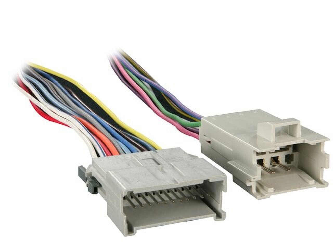
The 2006 Chevy Trailblazer radio wiring harness connects the factory radio (or an aftermarket replacement) to the vehicle's electrical system and speakers. It typically consists of two main connectors:
- Power and Ground Connector: This connector handles the power supply to the radio, the ground connection, and often includes accessory power (switched power that turns on and off with the ignition).
- Speaker Connector: This connector carries the audio signals from the radio to the individual speakers in the vehicle. Typically, there are four pairs of wires: front left, front right, rear left, and rear right. Each pair consists of a positive (+) and negative (-) wire.
Here are some key components and circuits you'll find in the harness:
- 12V Constant (Battery): This wire provides constant power to the radio, even when the ignition is off. It's used for features like clock memory and preset station storage.
- 12V Switched (Accessory): This wire provides power to the radio only when the ignition is turned on. It's typically connected to the ignition switch via an accessory power circuit.
- Ground: This wire provides the return path for the electrical current, completing the circuit. It's typically connected to the vehicle's chassis.
- Illumination: This wire dims the radio display when the headlights are turned on. It's connected to the headlight switch.
- Antenna Power (Remote Turn-On): This wire provides power to the antenna amplifier when the radio is turned on. It's also commonly used to turn on aftermarket amplifiers.
- Speakers (Front Left/Right, Rear Left/Right): These wires carry the audio signals from the radio to the speakers. Each speaker has a positive (+) and negative (-) wire. Incorrect speaker polarity can cause poor sound quality and even damage to the speakers.
- Data Bus Wires (if applicable): Some newer vehicles use a data bus (like CAN bus) to communicate between the radio and other vehicle systems. These wires allow the radio to display information from the vehicle's computer, such as climate control settings or vehicle speed. The 2006 Trailblazer does not heavily rely on this feature for the radio, but some models with more advanced features may have it.
Understanding Wiring Diagram Symbols and Color Codes
Wiring diagrams use symbols and color codes to represent different components and wires. Understanding these conventions is crucial for interpreting the diagram correctly.
Symbols:
- Solid Line: Represents a wire.
- Dashed Line: May represent a shielded cable or a ground connection.
- Circles: Indicate connection points or splices.
- Squares: Often represent connectors or terminals.
- Resistor Symbol (Zigzag Line): Represents a resistor, which limits the flow of current.
- Capacitor Symbol (Two Parallel Lines): Represents a capacitor, which stores electrical energy.
- Ground Symbol (Downward-Pointing Pyramid): Represents a connection to the vehicle's chassis ground.
Color Codes:
Automotive wiring harnesses use color-coded wires to identify the function of each wire. While there isn't a strict universal standard, some colors are commonly used for specific functions. Here's a general guide, but always refer to the specific wiring diagram for your vehicle:
- Red: Typically used for 12V constant (battery) power.
- Yellow: Often used for 12V switched (accessory) power.
- Black: Almost always used for ground.
- Blue: Frequently used for antenna power (remote turn-on) or amplifier remote.
- White: Can be used for various signals, but often associated with speaker wires. Refer to diagram for exact purpose.
- Green: Often used for speaker wires. Refer to diagram for exact purpose.
- Gray: Typically used for illumination.
- Brown: Can be used for various signals, but often associated with speaker wires. Refer to diagram for exact purpose.
Wiring diagrams typically use abbreviations for colors, such as:
- RED: Red
- BLK: Black
- YEL: Yellow
- BLU: Blue
- GRN: Green
- WHT: White
- GRY: Gray
- BRN: Brown
Also, you may see color combinations, like WHT/BLU (White with a Blue stripe).
How the Radio Wiring Harness Works
The radio wiring harness acts as the central nervous system for your car's audio. The 12V constant wire keeps the radio's memory alive, storing your presets and settings. When you turn the ignition key, the 12V switched wire energizes the radio's main power circuit. The radio then draws power from the battery through these wires to power its internal components, including the amplifier, tuner, and display. The ground wire provides the return path for the current, completing the circuit.
When you select a radio station or a music source, the radio's internal amplifier sends audio signals through the speaker wires to the individual speakers. Each speaker receives a positive and negative signal, which vibrates the speaker cone and produces sound.
The illumination wire dims the radio's display when you turn on the headlights, reducing glare at night. The antenna power wire activates the antenna amplifier, boosting the radio signal strength.
Real-World Use and Basic Troubleshooting
Here are some basic troubleshooting tips when working with the radio wiring harness:
- No Power to Radio: Check the 12V constant and 12V switched wires with a multimeter to ensure they're receiving power. Also, check the ground connection for continuity. Inspect the radio fuse in the fuse box and replace if blown.
- No Sound from Speakers: Check the speaker wires for continuity with a multimeter. Ensure the speaker wires are properly connected to the speakers. Also, check the radio's fader and balance settings to make sure the sound isn't being directed to only one speaker.
- Intermittent Audio: Check the wiring harness connectors for loose or corroded terminals. Clean the terminals with electrical contact cleaner and reassemble the connectors securely.
- Distorted Audio: Check the speaker wires for shorts to ground or other wires. Replace any damaged wires. Ensure that the speakers are not blown or damaged.
- Radio Turns Off When Volume is High: This indicates a potential issue with the amplifier not receiving enough current. This could be a weak 12V constant wire, a bad ground or the radio pulling too much power.
Safety Considerations
Working with automotive electrical systems can be dangerous if you don't take proper precautions. Here are some safety tips:
- Disconnect the Battery: Before working on any electrical components, disconnect the negative terminal of the battery. This will prevent accidental shorts and electrical shocks.
- Use a Multimeter: Use a multimeter to test wires and circuits before disconnecting or cutting them. This will help you identify the function of each wire and avoid damaging components.
- Use Proper Tools: Use properly insulated tools designed for automotive electrical work. This will help prevent electrical shocks and damage to the wiring harness.
- Avoid Working in Wet Conditions: Never work on electrical systems in wet or damp conditions. Water is a conductor of electricity and can increase the risk of electrical shock.
- Protect Yourself: Wear safety glasses and gloves to protect yourself from potential hazards.
- Be Careful with Airbags: The SRS (Supplemental Restraint System, i.e., airbags) wiring is often located near the radio wiring. Accidentally triggering an airbag can cause serious injury. Disconnect the battery and wait at least 10 minutes before working near the SRS wiring.
Remember, the 12V constant wire is always live, even when the ignition is off. Be careful not to short this wire to ground, as it can damage the vehicle's electrical system.
Download the Wiring Diagram
Now that you have a solid understanding of the 2006 Chevy Trailblazer radio wiring harness, you're ready to tackle your audio upgrade or repair project with confidence. To help you further, we have the complete wiring diagram available for you to download. With this diagram in hand, you'll have all the information you need to identify the function of each wire and ensure a safe and successful installation. Good luck!
(Download link would go here – Replace this with the actual link)