2006 Chrysler 300 5.7 Engine Wiring Harness
Alright, let's dive into the wiring harness for the 2006 Chrysler 300's 5.7L Hemi engine. This is crucial knowledge for anyone looking to diagnose electrical issues, perform modifications, or simply understand how the engine's systems communicate with each other. We're going to break down the key aspects of the wiring harness, explain its functions, and provide some practical troubleshooting tips. Think of this as your roadmap to electrical success under the hood.
Purpose: Why Bother with the Wiring Diagram?
Why should you care about the wiring harness diagram? Simply put, it's essential for any serious engine work, especially when it involves electrical components. Here's why:
- Diagnostics: When your 300 is throwing codes or exhibiting strange behavior, a wiring diagram helps you trace the signal path and pinpoint the faulty sensor, actuator, or wiring. Trying to diagnose electrical problems without a diagram is like navigating a maze blindfolded.
- Repairs: Damage to the wiring harness is common, whether from rodent attacks, chafing, or accidental cuts. The diagram shows you how wires are routed, what connectors they use, and how to properly splice or replace damaged sections.
- Modifications: Planning to install aftermarket parts like performance chips, gauges, or forced induction? You'll need to tap into the existing wiring system. The diagram reveals the correct wires to use and ensures you don't accidentally damage sensitive components.
- Understanding the System: Even if you're not actively working on the car, understanding the wiring harness improves your overall knowledge of the engine's control systems. You'll be able to better interpret diagnostic data and make informed decisions about repairs and upgrades.
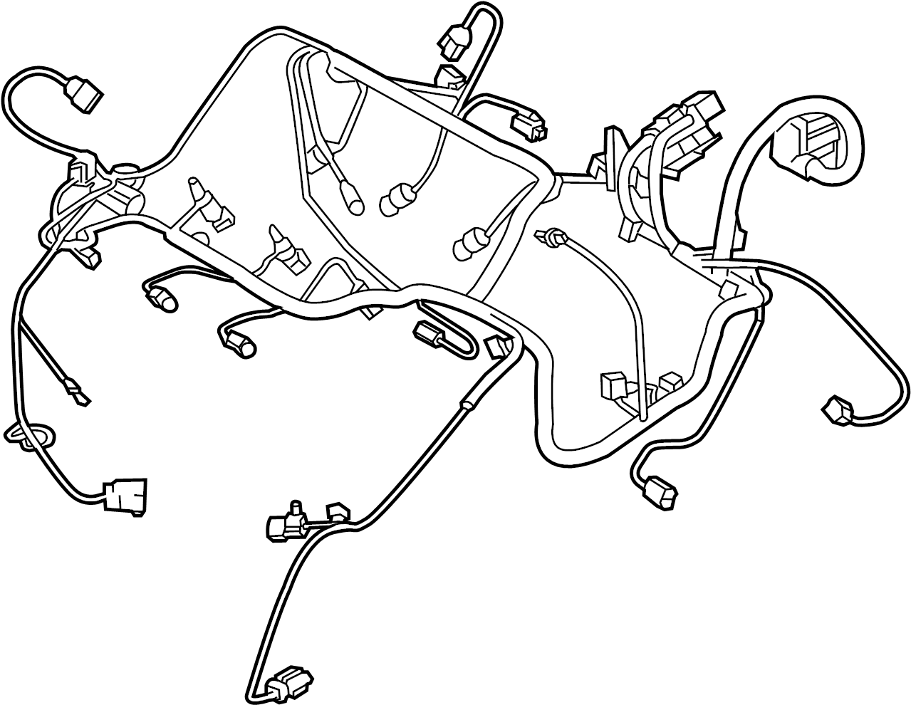
Key Specs and Main Parts
The 2006 Chrysler 300's 5.7L Hemi engine wiring harness is a complex network of wires, connectors, and sensors. Let's break down some of the key specs and main parts:
- Engine Control Module (ECM): The brain of the operation. The ECM receives signals from various sensors, processes the data, and controls actuators like fuel injectors, ignition coils, and the throttle body.
- Sensors: These are the eyes and ears of the engine. Critical sensors include:
- Crankshaft Position Sensor (CKP): Measures the crankshaft's position and speed.
- Camshaft Position Sensor (CMP): Measures the camshaft's position.
- Manifold Absolute Pressure (MAP) Sensor: Measures the pressure inside the intake manifold.
- Throttle Position Sensor (TPS): Measures the throttle plate's angle.
- Oxygen (O2) Sensors: Measure the oxygen content in the exhaust stream (both upstream and downstream of the catalytic converters).
- Engine Coolant Temperature (ECT) Sensor: Measures the engine coolant temperature.
- Actuators: These are the engine's muscles. Critical actuators include:
- Fuel Injectors: Control the amount of fuel injected into the cylinders.
- Ignition Coils: Generate the high-voltage spark that ignites the air-fuel mixture.
- Throttle Body: Controls the amount of air entering the engine.
- Idle Air Control (IAC) Valve: Regulates the engine's idle speed.
- Connectors: These are the interfaces between the wiring harness and the various components. They're designed to be secure and weather-resistant. Common types include:
- Weatherpack Connectors: Sealed connectors used in harsh environments.
- Molex Connectors: Versatile connectors used for various applications.
- Deutsch Connectors: High-quality, heavy-duty connectors.
- Wiring: The arteries and veins of the system. The wires are typically color-coded to help identify their function. Wire gauge (thickness) is also important; thinner wires are used for low-current signals, while thicker wires are used for high-current power and ground circuits.
Understanding the Wiring Diagram: Symbols, Lines, and Colors
The wiring diagram is a schematic representation of the electrical system. It uses a standardized set of symbols, lines, and colors to convey information. Here's a breakdown:
- Lines: Represent wires or connections.
- Solid Lines: Typically represent a single wire.
- Dashed Lines: Often indicate shielded wires or ground connections.
- Colors: Each wire is typically identified by a color code. For example:
- RD: Red
- BK: Black
- WT: White
- GN: Green
- BL: Blue
- YL: Yellow
- Symbols: Represent electrical components. Common symbols include:
- Resistors: Zigzag line.
- Capacitors: Two parallel lines.
- Diodes: Triangle pointing to a line.
- Relays: Coil and switch.
- Ground: Series of lines ending in a point.
- ECM: Often represented as a box with pins labeled for inputs and outputs.
- Sensors and Actuators: Varied symbols depending on the specific component. Usually some kind of circle/oval with a letter inside (like "T" for temperature).
Understanding these symbols and color codes is crucial for navigating the wiring diagram and tracing circuits. Take your time to familiarize yourself with the legend provided on the diagram.
How It Works: The Flow of Electricity and Information
The 5.7L Hemi engine's electrical system is a closed-loop control system. The ECM constantly monitors the engine's operating conditions through various sensors. It then uses this information to adjust the actuators, optimizing performance, fuel efficiency, and emissions. Here's a simplified overview:
- Sensors Provide Input: Sensors like the CKP, CMP, MAP, and TPS send signals to the ECM. These signals represent critical parameters like engine speed, camshaft position, manifold pressure, and throttle position.
- ECM Processes Data: The ECM analyzes the sensor data and compares it to pre-programmed values in its memory.
- Actuators Respond: Based on the analysis, the ECM sends signals to the actuators, such as the fuel injectors and ignition coils. The fuel injectors control the amount of fuel injected into the cylinders, while the ignition coils control the timing and duration of the spark.
- Feedback Loop: Oxygen sensors in the exhaust stream provide feedback on the combustion process. The ECM uses this feedback to further refine the fuel mixture and ignition timing.
This continuous feedback loop ensures that the engine operates efficiently and effectively under various driving conditions.
Real-World Use: Basic Troubleshooting Tips
So, how can you use this knowledge in the real world? Here are some basic troubleshooting tips:
- Start with the Basics: Before diving into the wiring diagram, check the basics. Make sure the battery is fully charged, the fuses are intact, and the connections are clean and secure.
- Use a Multimeter: A multimeter is your best friend when troubleshooting electrical problems. Use it to check for voltage, continuity, and resistance.
- Follow the Wiring Diagram: Trace the circuit from the power source to the component in question. Look for breaks in the wiring, loose connections, or short circuits.
- Check for Ground Faults: A ground fault occurs when a wire accidentally touches the vehicle's chassis. This can cause a short circuit and damage to the wiring harness. Use a multimeter to check for continuity between the wire and ground.
- Scan for Diagnostic Trouble Codes (DTCs): Use an OBD-II scanner to read any stored DTCs. These codes can provide valuable clues about the nature and location of the problem.
Important Note: When working on electrical systems, always disconnect the negative battery cable to prevent accidental short circuits.
Safety: Risky Components and Precautions
Working with automotive electrical systems can be dangerous. Here are some safety precautions to keep in mind:
- Airbag System: The airbag system contains highly sensitive components. Never probe the airbag wiring with a multimeter or other tools unless you're specifically trained to do so. Accidental activation of the airbag can cause serious injury.
- High-Voltage Circuits: The ignition system generates high voltage. Avoid touching the ignition coils or spark plug wires while the engine is running.
- Fuel System: The fuel system is pressurized. Use caution when working on fuel injectors or fuel lines. Always relieve the pressure before disconnecting any components.
- Proper Tools: Use insulated tools designed for automotive electrical work.
- Disconnect the Battery: As mentioned before, always disconnect the negative battery cable before working on any electrical component.
Always prioritize safety when working on your car's electrical system. If you're not comfortable performing a particular task, seek the help of a qualified mechanic.
Understanding the 2006 Chrysler 300 5.7L engine wiring harness is a valuable skill for any car enthusiast or DIY mechanic. By familiarizing yourself with the diagram, understanding the symbols and color codes, and following proper safety precautions, you can confidently diagnose and repair electrical problems. We have the wiring diagram file ready for you to download, giving you a comprehensive tool for all your electrical repairs.