
2006 Chrysler Sebring Fuse Box Diagram
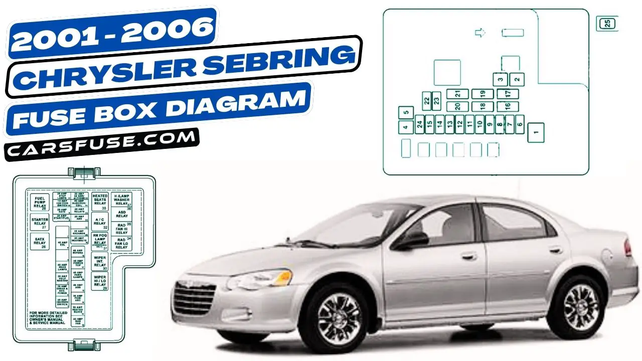
The 2006 Chrysler Sebring, a popular mid-size car of its time, relies heavily on its electrical system for everything from starting the engine to powering the radio. Understanding the fuse box diagram is crucial for effective troubleshooting, repairs, and even simple modifications. This article will serve as a comprehensive guide to interpreting the Sebring's fuse box diagram, providing you with the knowledge to diagnose electrical issues confidently.
Purpose: Why You Need This Diagram
Imagine your Sebring's headlights suddenly stop working, or the power windows refuse to roll down. Without a fuse box diagram, you're essentially stumbling in the dark. The diagram acts as a road map to your car's electrical system, allowing you to quickly identify and locate the correct fuse or relay responsible for a particular circuit. This knowledge empowers you to:
- Diagnose Electrical Problems: Pinpoint the source of electrical malfunctions by identifying blown fuses.
- Perform Repairs: Replace faulty fuses or relays with the correct replacements, restoring functionality.
- Safely Modify Electrical Systems: When adding aftermarket accessories (like a new sound system or auxiliary lighting), you can use the diagram to tap into appropriate circuits without overloading the system.
- Understand Your Car's Electrical Architecture: Gain a deeper understanding of how different components are interconnected and powered.
Attempting to repair electrical issues without a proper diagram can lead to further damage, short circuits, or even fires. Don't take the risk!
Key Specs and Main Parts
The 2006 Chrysler Sebring typically has two main fuse boxes: one located in the interior of the car (usually under the dashboard on the driver's side) and another under the hood, often near the battery. Each fuse box contains a variety of fuses and relays, each protecting a specific circuit within the car's electrical system.
Fuse Box Locations:
- Interior Fuse Box (Junction Block): This houses fuses and relays for interior components like the radio, power windows, climate control, and instrument panel.
- Under-Hood Fuse Box (Power Distribution Center or PDC): This box protects circuits related to the engine, headlights, anti-lock braking system (ABS), and other critical systems.
Key Components:
- Fuses: These are sacrificial devices designed to protect circuits from overcurrent. A blown fuse indicates a problem in the circuit it protects. Fuses are rated in amperes (amps), indicating the maximum current they can handle before blowing.
- Relays: These are electromechanical switches that control high-current circuits using a low-current signal. They are often used to control things like headlights, starter motors, and fuel pumps.
- Circuit Breakers: Some circuits might use circuit breakers, which are reusable protection devices that automatically interrupt the circuit during an overload and can be reset after the problem is resolved.
Symbols: Interpreting the Diagram
Fuse box diagrams use a standardized set of symbols and conventions to represent different components and their functions. Understanding these symbols is essential for accurate interpretation.
Lines and Connections:
- Solid Lines: Represent electrical wires.
- Dotted Lines: May represent ground connections or connections to specific modules.
- Intersections: A dot at the intersection of two lines indicates a connection; otherwise, the lines are not electrically connected.
Fuse and Relay Symbols:
- Fuse Symbol: Typically a squiggly line inside a rectangle. The amperage rating is usually indicated next to the symbol.
- Relay Symbol: Consists of a coil symbol (representing the relay's electromagnet) and a switch symbol (representing the contacts that the relay controls).
Component Icons:
The diagram will often include icons representing the specific components powered by each circuit. For example:
- Headlight Icon: Indicates the fuse protects the headlight circuit.
- Radio Icon: Indicates the fuse protects the radio circuit.
- Window Icon: Indicates the fuse protects the power window circuit.
Color Coding (If Applicable):
Some diagrams may use color coding to further differentiate circuits. For example, a specific color might indicate circuits related to the anti-lock braking system (ABS) or airbags. However, color coding is not always consistent, so rely primarily on the symbols and labels.
How It Works: Following the Circuit
The fuse box diagram allows you to trace the flow of electricity from the battery, through the fuse or relay, and to the component it powers. By understanding this flow, you can pinpoint the source of a problem. For example, if your headlights are not working, you would:
- Consult the fuse box diagram to identify the fuse(s) associated with the headlights.
- Locate the fuse(s) in the fuse box.
- Visually inspect the fuse(s) for a broken filament. If the filament is broken, the fuse is blown.
- If the fuse is blown, replace it with a fuse of the exact same amperage rating.
- If the fuse blows again immediately after replacement, there is likely a short circuit in the headlight wiring or in the headlight itself. Further investigation is needed.
Real-World Use: Basic Troubleshooting Tips
Here are some practical troubleshooting tips using the fuse box diagram:
- Start with the Simplest Solution: Always check the fuses before assuming a more complex problem.
- Visual Inspection: Look for blown fuses (broken filament), corroded terminals, or signs of overheating.
- Fuse Tester: Use a fuse tester to quickly check the continuity of a fuse without removing it.
- Multimeter: A multimeter can be used to measure voltage and current, helping you diagnose more complex electrical problems.
- Replace with the Correct Amperage: Never replace a fuse with one of a higher amperage rating. This can overload the circuit and cause a fire.
- Document Your Findings: Keep a record of the fuses you've checked and the results. This can help you track down intermittent problems.
Pro Tip: Keep a spare set of fuses in your glove compartment. You never know when you might need one!
Safety: Important Considerations
Working with electrical systems can be dangerous. Here are some important safety precautions:
- Disconnect the Battery: Before working on any electrical components, disconnect the negative terminal of the battery to prevent short circuits and electrical shocks.
- Avoid Working in Wet Conditions: Water conducts electricity, increasing the risk of electric shock.
- Use Insulated Tools: Use tools with insulated handles to protect yourself from electric shock.
- Be Aware of Airbag Circuits: Airbag circuits are particularly sensitive and can be triggered accidentally if not handled carefully. Consult the service manual for specific instructions on disabling the airbag system before working on any related wiring. This is extremely important and should not be taken lightly. Accidental deployment can cause serious injury.
- High-Current Components: Be extremely careful when working with circuits involving high-current components like the starter motor or alternator. These components can deliver a powerful shock.
Always remember, if you're not comfortable working with electrical systems, it's best to consult a qualified mechanic.
Understanding the 2006 Chrysler Sebring fuse box diagram is a valuable skill for any car owner. By using this guide, you can confidently diagnose and repair many common electrical problems, saving you time and money. Remember to always prioritize safety and consult a professional when needed.
We have the full, detailed 2006 Chrysler Sebring Fuse Box Diagram available for download. This diagram will provide you with the exact fuse and relay locations, amperage ratings, and component designations for both the interior and under-hood fuse boxes. This resource will be invaluable for your troubleshooting and repair efforts. Download the file and keep it handy in your garage or toolbox.