2006 Dodge Charger Fuse Box Diagram Under Hood
The 2006 Dodge Charger, a modern muscle car, relies on a complex electrical system protected by a network of fuses and relays. Understanding the under-hood fuse box diagram is crucial for anyone undertaking DIY repairs, modifications, or even basic troubleshooting. This article will provide a detailed explanation of the 2006 Dodge Charger's under-hood fuse box, empowering you to diagnose and resolve electrical issues confidently.
Purpose of the Under-Hood Fuse Box Diagram
The fuse box diagram serves as a roadmap for the vehicle's electrical system. Its primary purpose is to help you quickly identify the fuse or relay associated with a specific electrical component. Imagine your headlights suddenly stop working. Without a diagram, you'd have to tediously test each fuse. With the diagram, you can quickly locate the fuse labeled "Headlights," inspect it, and replace it if necessary. This saves time, prevents misdiagnosis, and avoids potentially damaging other electrical components.
More specifically, the diagram is indispensable for:
- Troubleshooting electrical problems: Identifying blown fuses or faulty relays causing malfunctions.
- Performing electrical repairs: Replacing damaged fuses or relays accurately.
- Installing aftermarket accessories: Tapping into the correct circuits for power.
- Understanding the vehicle's electrical system: Gaining a deeper understanding of how different components are powered and protected.
- Preventing electrical fires: Ensuring the correct amperage fuses are installed.
Key Specs and Main Parts of the 2006 Dodge Charger Under-Hood Fuse Box
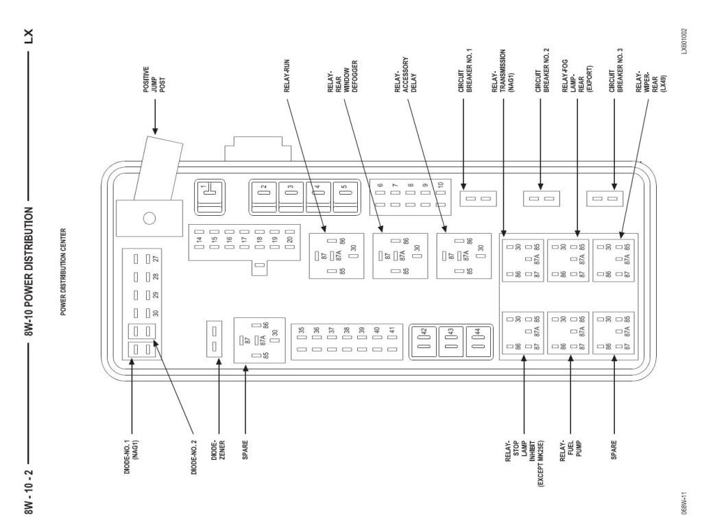
The 2006 Dodge Charger's under-hood fuse box is typically located in the engine compartment, usually on the driver's side near the battery. Its exact location can vary slightly depending on the engine option (2.7L, 3.5L, 5.7L, or 6.1L), so always double-check your owner's manual. The fuse box itself is a black plastic housing with a removable cover. The cover usually has the fuse diagram printed on the inside.
Key components within the fuse box include:
- Fuses: These are the sacrificial components designed to protect circuits from overcurrent. They contain a thin wire that melts and breaks the circuit if the current exceeds a predetermined amperage. Fuses are rated in amps (Amperes) and come in different sizes and types (e.g., mini blade, ATO blade).
- Relays: These are electromechanical switches that control high-current circuits using a low-current signal. They allow the car's computer to control powerful devices like the fuel pump, starter motor, and air conditioning compressor.
- Circuit Breakers: Some circuits may use circuit breakers, which are resettable overcurrent protection devices. Unlike fuses, they don't need to be replaced; they simply need to be reset after tripping. They are less common than fuses in the under-hood fuse box.
- Wiring Harness Connectors: These connect the fuse box to the vehicle's electrical system, distributing power to various components.
Understanding Fuse Box Diagram Symbols
The fuse box diagram uses symbols and abbreviations to represent different electrical components and circuit characteristics. Deciphering these symbols is essential for accurate troubleshooting.
Common Symbols:
- Solid Lines: Typically represent the main power feed or ground connections.
- Dashed Lines: Often indicate control circuits or signal lines.
- Rectangles: Represent relays.
- Small Rectangles or Squares with Numbers: Represent fuses, with the number indicating the amperage rating (e.g., "20" means a 20-amp fuse).
- Circles: Can represent various sensors or switches depending on the context.
- Icons: Specific icons are used to represent different components, such as a light bulb for headlights, a fan for the cooling fan, and so on. Check the legend on the diagram for a complete list of icons.
Colors:
Wire colors are often included in the diagram to help identify specific circuits. The most common colors include:
- Red: Typically indicates a hot (positive) power wire.
- Black: Typically indicates a ground wire (negative).
- Other Colors: Varying colors represent different circuits and functions. The legend on the diagram will specify what each color represents.
Understanding these symbols and colors allows you to trace circuits and identify the components responsible for a particular function.
How It Works: The Electrical Circuit
To fully understand the fuse box, it's essential to grasp the concept of an electrical circuit. A circuit is a closed loop that allows electrical current to flow from a power source (the battery) through a load (e.g., a headlight) and back to the power source.
The fuse sits within this circuit, acting as a safety device. If there is an overcurrent condition (e.g., a short circuit), the fuse blows, breaking the circuit and preventing damage to the wiring and components. The amperage rating of the fuse is carefully chosen to protect the circuit without unnecessarily interrupting normal operation.
Relays, on the other hand, act as remote switches. A low-current signal from the car's computer activates the relay, which then closes a high-current circuit to power a device. This allows the computer to control devices that draw a lot of power without having to handle the high current directly.
Real-World Use: Basic Troubleshooting Tips
Here are some basic troubleshooting tips using the fuse box diagram:
- Identify the problem: Determine which electrical component is malfunctioning.
- Consult the diagram: Locate the fuse or relay associated with the faulty component on the diagram.
- Inspect the fuse: Visually inspect the fuse for a broken filament. A blown fuse will typically have a visible break in the wire. Use a multimeter to confirm continuity (or lack thereof).
- Replace the fuse: If the fuse is blown, replace it with a new fuse of the exact same amperage rating. Never use a higher amperage fuse, as this could damage the circuit.
- Test the component: After replacing the fuse, test the component to see if it now works. If the fuse blows again immediately, there is likely a short circuit in the wiring or the component itself.
- Check the relay: If the fuse is good, but the component still doesn't work, the relay may be faulty. You can test the relay using a multimeter or by swapping it with a known good relay of the same type.
Safety: Identifying Risky Components
Working with the vehicle's electrical system can be dangerous if proper precautions are not taken. Certain components and circuits carry high voltage or current and should be handled with extreme care. Pay close attention to these areas:
- Battery: The battery contains corrosive acid and can produce explosive gases. Always disconnect the negative terminal before working on the electrical system to prevent shorts and potential explosions.
- High-Current Circuits: Circuits that power components like the starter motor, alternator, and air conditioning compressor carry high current. Avoid touching exposed wires or terminals in these circuits.
- Airbag System: The airbag system is a sensitive and potentially dangerous system. Never attempt to repair or modify the airbag system without proper training and equipment. Consult a qualified technician.
Important Safety Note: Always disconnect the negative battery cable before working on the electrical system. Wear appropriate safety gear, such as safety glasses and gloves. If you are not comfortable working on the electrical system, consult a qualified mechanic.
Remember to consult your owner's manual for specific instructions and warnings related to your vehicle. Taking your time and being careful will ensure a safe and successful repair.
To further assist you in your repair endeavors, we have a digital copy of the 2006 Dodge Charger Under-Hood Fuse Box Diagram. You can download it and use it to quickly reference which fuse belongs to the circuit in question.