2006 Dodge Ram Stereo Wiring Diagram
Let's dive into the wiring of the 2006 Dodge Ram's stereo system. Whether you're looking to upgrade your head unit, troubleshoot a speaker issue, or simply understand how the audio system is wired, this article will be your guide. Having access to and understanding the wiring diagram is crucial. We'll break down the components, explain the symbols, and give you practical troubleshooting tips. Plus, we have the complete 2006 Dodge Ram stereo wiring diagram available for download.
Purpose of the Wiring Diagram
The wiring diagram for the 2006 Dodge Ram's stereo isn't just a piece of paper; it's your roadmap to understanding the intricate network of wires that bring sound to your ears. It serves several vital purposes:
- Repairing Existing Problems: If a speaker isn't working, the radio doesn't power on, or the sound quality is poor, the diagram helps you trace the fault.
- Upgrading the System: Want to install a new head unit, amplifier, or speakers? The diagram shows you where to tap into existing wires and ensure compatibility.
- Adding Aftermarket Accessories: Thinking about adding a subwoofer, satellite radio, or a backup camera? The diagram helps you find the correct power, ground, and signal wires.
- Learning the System: Even if you don't have immediate plans for repairs or upgrades, understanding the diagram gives you a deeper knowledge of your vehicle's electrical system.
Key Specs and Main Parts
The 2006 Dodge Ram, depending on the trim level, came with a few different stereo configurations. The base system typically included an AM/FM radio with a CD player and four speakers. Higher trim levels could include a premium sound system with an amplifier and additional speakers. Here are some key components that the wiring diagram will illustrate:
- Head Unit (Radio): The central control unit, responsible for receiving radio signals, playing CDs, and processing audio signals. The wiring diagram shows its power, ground, speaker outputs, and any communication lines (like CAN bus).
- Speakers: Usually located in the doors, dashboard, and sometimes the rear pillars or deck. The diagram shows the polarity (+ and -) for each speaker connection to ensure proper phasing.
- Amplifier (if equipped): Boosts the audio signal from the head unit to drive the speakers with more power. The diagram shows its power source, ground, input signals from the head unit, and output signals to the speakers.
- Wiring Harnesses and Connectors: Bundles of wires and their corresponding connectors. The diagram identifies the pinout (arrangement of pins) for each connector, which is critical for making proper connections.
- Antenna: Receives radio signals. The diagram shows its connection to the head unit.
Symbols and Terminology Explained
Understanding the symbols used in the wiring diagram is essential for interpreting it correctly. Here's a breakdown of common symbols and terms:
- Solid Lines: Represent wires. The thickness of the line sometimes (but not always consistently) indicates the wire gauge (thickness).
- Dotted Lines: Often represent shielded cables or communication buses (like CAN bus – Controller Area Network, a communication protocol that allows different electronic control units (ECUs) in a vehicle to communicate with each other).
- Colors: Each wire is assigned a color code (e.g., Red, Black, Blue/White). These codes are crucial for identifying wires in the actual harness. The diagram legend will detail what each color represents.
- GND or Ground Symbol: Indicates a connection to the vehicle's chassis, providing a return path for electrical current.
- +12V or B+: Indicates a connection to the vehicle's battery positive terminal (often through a fuse).
- Connectors: Shown as squares or circles with numbers inside. These numbers indicate the pin numbers within the connector.
- Fuses: Represented by a symbol resembling a zigzag line within a rectangle. They protect circuits from overcurrent.
- Resistors: Shown as a zigzag line. Used to limit current flow.
- Capacitors: Two parallel lines, one curved. Used to store electrical energy.
- Diodes: A triangle pointing to a vertical line. Allows current to flow in one direction only.
- Switches: Show the physical switch and the circuit it controls.
Understanding wire color codes is paramount. For example, if the diagram shows a Blue/White wire, it means the wire is primarily blue with a white stripe. Always refer to the diagram's legend to confirm the specific meaning of each color combination.
How It Works: A Circuit's Journey
Let's trace a simple circuit – the power supply to the head unit. The process starts at the battery. A +12V wire runs from the battery (often through a fuse in the fuse box) to the head unit. This provides the main power. There's also usually an "ignition" wire that's only powered when the ignition key is in the "accessory" or "on" position. This allows the radio to turn on and off with the car. The head unit also needs a ground connection, which is typically a wire connected to the vehicle's chassis. This completes the circuit.
When you turn on the radio, the head unit draws power and processes audio signals from the antenna, CD player, or other sources. The processed signals are then sent to the speakers (either directly or through an amplifier). The wiring diagram shows the path of each signal, the connectors it passes through, and the color codes of the wires involved.
Real-World Use: Basic Troubleshooting Tips
Here are a few troubleshooting scenarios where the wiring diagram can be invaluable:
- No Power to the Radio: Check the fuse (using the diagram to identify the correct one). If the fuse is good, use a multimeter to check for voltage at the head unit's power and ground wires. If there's no voltage, trace the wiring back towards the fuse box, checking for broken or disconnected wires.
- Speaker Not Working: First, check the speaker itself (swap it with a known working speaker). If the speaker is good, use a multimeter to check for continuity in the speaker wires. The wiring diagram shows the path of the wires from the head unit (or amplifier) to the speaker. Check the connections at both ends.
- Distorted Sound: Could be a faulty speaker, a bad connection, or a problem with the head unit or amplifier. The diagram can help you isolate the problem by tracing the signal path and checking the connections.
- Interference: Locate the shielding of the wires using the wiring diagram to make sure they are grounded correctly.
Important Tip: Before working on any electrical system, disconnect the negative terminal of the battery to prevent shorts and potential damage.
Safety Considerations
Working with automotive electrical systems can be dangerous. Here are some key safety precautions:
- Disconnect the Battery: Always disconnect the negative terminal of the battery before working on any electrical system.
- Use Proper Tools: Use insulated tools and a multimeter to avoid shocks and shorts.
- Avoid Working in Wet Conditions: Water and electricity are a dangerous combination.
- Identify High-Current Circuits: Be extra careful when working with circuits that carry high current, such as the power supply to the amplifier. These circuits can generate heat and pose a fire hazard if shorted.
- Airbags: Be aware of airbag locations and follow recommended safety procedures to prevent accidental deployment. Airbag circuits are typically yellow or orange, and you should avoid disturbing them unless you are a qualified technician.
The 2006 Dodge Ram stereo system, particularly if equipped with a factory amplifier, can have relatively high-voltage speaker outputs. Treat the wiring with respect, and double-check your connections.
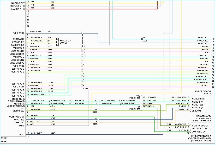
We have the complete 2006 Dodge Ram Stereo Wiring Diagram available for download. This diagram will provide a detailed visual representation of the system and help you navigate your repairs or upgrades with confidence.