2006 Gmc Sierra Radio Wiring Harness
For the intermediate car owner or budding DIY mechanic tackling audio upgrades, repairs, or simply understanding the electronics of their 2006 GMC Sierra, knowing the radio wiring harness is crucial. This article breaks down the specifics of the 2006 GMC Sierra radio wiring harness. Why is understanding this important? Whether you're installing a new head unit, diagnosing speaker issues, adding an amplifier, or simply want to trace a faulty wire, a solid grasp of the wiring diagram is invaluable. This article will cover the purpose, key specs, symbols, functionality, real-world uses, and safety considerations associated with this essential electrical component. We also have the complete wiring diagram available for download.
Purpose of the 2006 GMC Sierra Radio Wiring Harness
The radio wiring harness is the central nervous system of your Sierra's audio system. Its primary purpose is to provide a standardized and organized interface between the vehicle's electrical system and the factory (or aftermarket) head unit (radio). It allows for the transmission of power, ground, audio signals (to speakers), and control signals (like steering wheel controls or illumination dimming). Understanding the harness allows you to:
- Install an aftermarket radio: This is perhaps the most common reason for needing this information. Aftermarket radios typically use different connectors than the factory unit. Adapters utilizing the factory wiring harness allow for a plug-and-play installation without cutting or splicing wires.
- Repair a faulty radio or wiring: By identifying the specific function of each wire, you can diagnose breaks, shorts, or other electrical issues within the harness.
- Add amplifiers or other audio components: Knowing the signal pathways allows for the proper integration of external amplifiers, subwoofers, and other audio enhancements.
- Troubleshoot speaker problems: You can use a multimeter to test the continuity of the speaker wires and identify potential issues with the speakers themselves or the wiring leading to them.
- Implement custom modifications: For the more advanced DIYer, understanding the harness opens the door to custom modifications such as adding auxiliary inputs or integrating custom lighting effects.
Key Specs and Main Parts
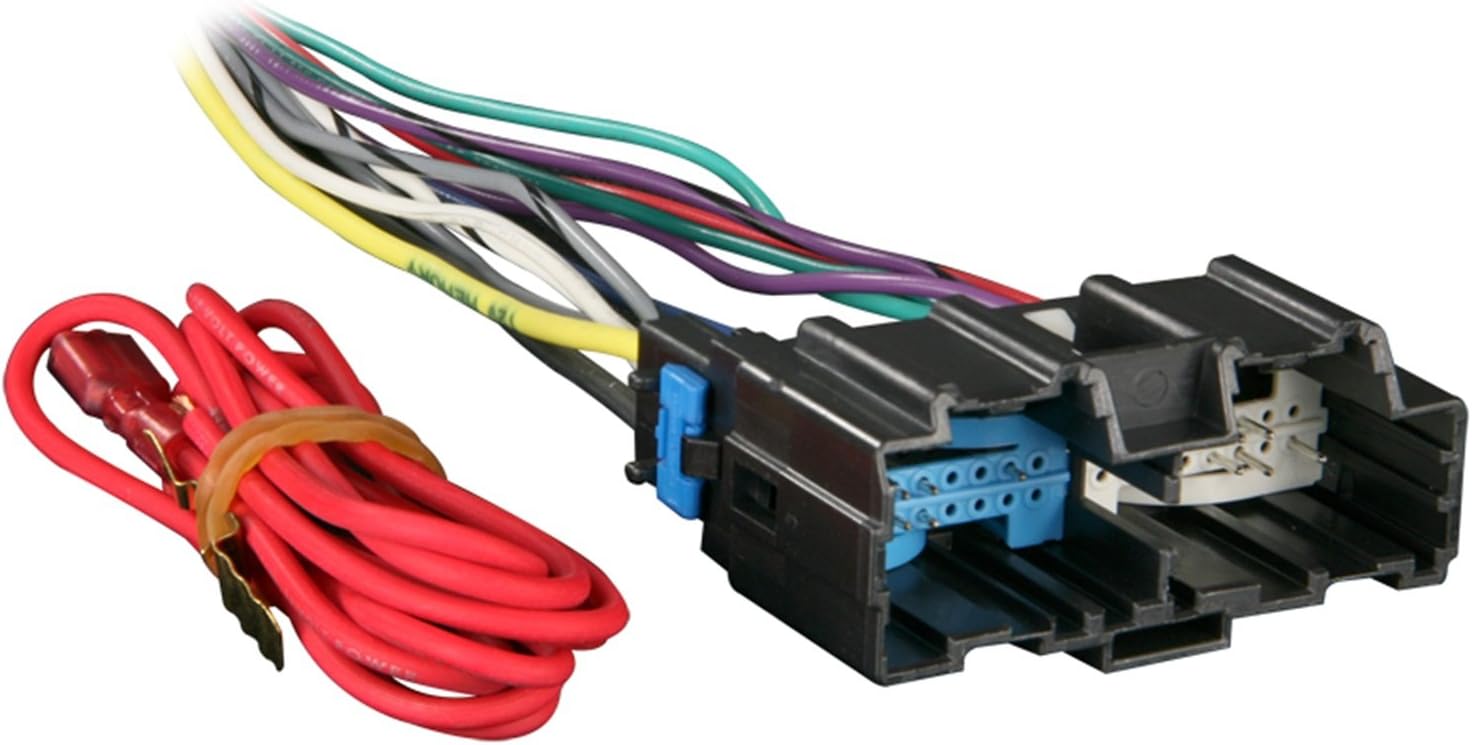
The 2006 GMC Sierra radio wiring harness typically consists of two main connectors that plug directly into the back of the factory radio. Here's a general overview of the key connections typically found in the harness. Actual color codes and pin assignments can vary slightly based on the specific Sierra trim level and options package, so always refer to the wiring diagram for your specific vehicle.
Main Parts and Connections
- Power Wires: These are 12V wires, providing constant and switched power to the radio. Typically, there's a constant 12V (for memory retention) and a switched 12V (that turns on with the ignition).
- Ground Wire: This provides the return path for the electrical current. A good ground connection is essential for proper radio operation.
- Speaker Wires: These carry the amplified audio signals from the radio to the speakers. There are typically four pairs of speaker wires: front left, front right, rear left, and rear right. Each pair consists of a positive (+) and a negative (-) wire.
- Illumination Wire: This wire dims the radio's display when the headlights are turned on.
- Antenna Wire: Connects the radio to the vehicle's antenna.
- Data Bus Wires (if equipped): Some Sierra models, especially those with premium audio systems or OnStar, may have data bus wires that communicate with other vehicle systems. This may include class 2 data.
Symbols, Lines, Colors and Icons
Understanding wiring diagrams relies on interpreting the symbols used. The diagram will have a color code chart. Some common color codes are listed below.
- Wires: Solid lines represent wires. Dashed lines may represent shielded cables or less critical connections. The thickness of the line has no significance.
- Colors: The color of each wire is typically indicated by a code (e.g., RED, BLU, GRN, YEL, etc.) printed along the wire line on the diagram. Use these color codes to verify you are working with the correct wire.
- Connectors: Connectors are depicted as rectangles or circles with lines extending from them, representing the wires entering or exiting the connector.
- Ground: The ground symbol is usually depicted as a series of descending lines, resembling an inverted Christmas tree.
- Fuses: Fuses are represented by a wavy line or a rectangular box with the fuse amperage rating indicated.
- Splices: Splices where two or more wires are joined are usually shown as a dot or a small circle where the lines intersect.
- Speakers: Speakers are represented by a circle with a cone inside.
Common color codes are listed below. Always refer to the actual diagram for your vehicle!
- BLK: Black
- RED: Red
- WHT: White
- GRY: Gray
- GRN: Green
- BLU: Blue
- YEL: Yellow
- BRN: Brown
- ORG: Orange
How It Works
The radio wiring harness serves as a conduit for electrical signals. When the ignition is turned on, the switched 12V wire provides power to the radio, activating it. The constant 12V wire maintains the radio's memory settings (e.g., station presets, volume levels). The ground wire completes the electrical circuit. The radio processes audio signals (from the antenna or other sources) and sends amplified signals to the speakers via the speaker wires. The illumination wire dims the radio's display when the headlights are activated, reducing glare at night. Any data bus wires present will communicate vehicle information to the radio, such as speed-dependent volume control or access to OnStar features.
Real-World Use: Basic Troubleshooting Tips
Here are a few basic troubleshooting tips:
- No Power to Radio: Check the fuses related to the radio (usually located in the under-hood fuse box or the interior fuse panel). Use a multimeter to verify that the constant and switched 12V wires are receiving power. Also, ensure the ground wire has a good connection to the vehicle's chassis.
- No Sound from Speakers: Use a multimeter to test the continuity of the speaker wires. Check the speaker connections at both the radio and the speaker itself. A broken wire or a loose connection could be the culprit.
- Distorted Sound: Distorted sound can be caused by a blown speaker, a shorted speaker wire, or a faulty amplifier (if equipped). Inspect the speakers for damage and check the speaker wires for any signs of shorts.
- Radio Turns Off and On: Check connections on the back of the unit and the constant power wire. The radio may be overheating.
Safety – Highlight Risky Components
Working with electrical components in a vehicle can be dangerous. Always disconnect the negative terminal of the battery before working on the radio wiring harness. This will prevent accidental shorts and potential damage to the vehicle's electrical system or personal injury. Pay close attention to the 12V power wires, as shorting these wires to ground can cause sparks, fires, and damage to the wiring harness or the radio. Be careful when cutting or splicing wires to avoid damaging the insulation or creating a short circuit. When making connections, use proper crimping tools and connectors to ensure a secure and reliable connection. Double-check all connections before reconnecting the battery.
Avoid working on the radio wiring harness in wet or damp conditions. Water can conduct electricity and increase the risk of electric shock. If you are not comfortable working with electrical components, it is best to consult a qualified mechanic or audio installer.
By understanding the purpose, components, symbols, and functionality of the 2006 GMC Sierra radio wiring harness, you're well-equipped to tackle audio upgrades, repairs, and troubleshooting tasks. Remember to always refer to the specific wiring diagram for your vehicle and prioritize safety when working with electrical components.
Remember, we have the complete wiring diagram file available. Contact us, and we can provide it to you.