2006 Grand Prix Radio Wiring Diagram
Alright, let's dive into the radio wiring diagram for the 2006 Pontiac Grand Prix. This isn't just a pretty picture; it's your roadmap to understanding, troubleshooting, and even upgrading the audio system in your ride. Whether you're dealing with a dead radio, planning a speaker upgrade, or adding an aftermarket amplifier, having a solid grasp of this diagram is crucial. We're going to break it down piece by piece, so even if you're not an electrical engineer, you'll be able to follow along.
Purpose of the 2006 Grand Prix Radio Wiring Diagram
The primary purpose of this diagram is to provide a visual representation of all the electrical connections within the radio system. Think of it as a detailed blueprint. It's invaluable for:
- Troubleshooting: Identifying the source of electrical problems (e.g., no power, distorted sound, speaker issues).
- Repairing: Locating damaged wires or connectors and making proper repairs.
- Upgrading: Planning and executing aftermarket installations (e.g., new head unit, amplifiers, speakers).
- Understanding: Gaining a deeper understanding of how the car's audio system is wired and functions.
Without this diagram, you'd be flying blind, potentially causing more damage than good. It's like trying to assemble furniture without the instructions – frustrating and likely to result in a less-than-perfect outcome.
Key Specs and Main Parts
The 2006 Grand Prix radio system, while relatively straightforward, has several key components. The wiring diagram will illustrate the connections between these parts:
- Head Unit (Radio Receiver): The brain of the system, controlling audio sources, volume, and tone. This diagram is for the stock head unit, but many principles apply if you are upgrading.
- Speakers: Responsible for producing sound. The Grand Prix typically has speakers in the front doors, rear deck, and sometimes tweeters in the A-pillars.
- Amplifier (if equipped): Some Grand Prix models have a factory amplifier, usually located in the rear of the car. This amplifies the signal from the head unit before sending it to the speakers.
- Wiring Harnesses: Bundles of wires that connect the various components.
- Connectors: Plastic plugs that allow for easy connection and disconnection of components.
- Grounding Points: Points where wires are connected to the car's chassis to provide a common ground. Proper grounding is essential for a functioning audio system.
Key specs to consider, though not explicitly on the diagram itself, include wire gauge (thickness) and voltage. Speaker wires are typically 16-18 gauge, while power and ground wires are usually thicker (12-14 gauge) to handle higher current. The system operates on the car's 12V DC electrical system. Understanding the polarity (positive and negative) is vital when making any connections.
Symbols: Deciphering the Diagram
Wiring diagrams use a variety of symbols to represent different components and connections. Here's a breakdown of some common ones:
- Solid Lines: Represent wires. The thickness of the line often indicates the wire gauge.
- Dotted Lines: May indicate shielding or connections that are not direct wires.
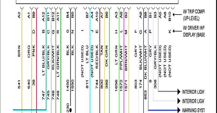
- Color Codes: Wires are typically color-coded (e.g., red, black, yellow, blue). The diagram will include a legend that lists the color codes and their corresponding functions. Understanding these color codes is crucial for identifying the correct wires.
- Ground Symbol: A symbol resembling an upside-down triangle or a series of horizontal lines decreasing in size. This indicates a connection to the car's chassis ground.
- Connector Symbols: Represented by squares or rectangles with pins inside. The diagram will show the pin numbers and their corresponding wire colors.
- Component Symbols: Each component (e.g., radio, speaker, amplifier) will have a specific symbol. These symbols are usually labeled with the component's name or function.
For example, a red wire might indicate a 12V power source, while a black wire usually represents ground. Remember to always refer to the color code legend on the diagram to avoid making incorrect connections.
How It Works: Signal Flow and Power Distribution
Let's trace the signal flow and power distribution in the 2006 Grand Prix radio system:
- Power Supply: The head unit receives power from the car's battery through the ignition switch or a constant power source. This provides the necessary energy to operate the radio and amplifier (if equipped).
- Audio Source Selection: The head unit allows you to select an audio source (e.g., AM/FM radio, CD player).
- Signal Processing: The head unit processes the audio signal, adjusting volume, tone, and balance.
- Amplification: If the car has a factory amplifier, the processed audio signal is sent to the amplifier for further amplification. Otherwise, the head unit's internal amplifier handles this task.
- Speaker Output: The amplified audio signal is then sent to the speakers, which convert the electrical signal into sound waves.
- Grounding: All components are properly grounded to the car's chassis to provide a stable electrical reference point and prevent noise.
The diagram will show how each of these steps is connected via wire. Understanding this flow helps in troubleshooting. If there's no sound from a particular speaker, you can trace the signal path from the head unit to the speaker to identify the point of failure.
Real-World Use: Basic Troubleshooting Tips
Here are a few basic troubleshooting tips using the wiring diagram:
- No Power to Radio: Check the power and ground connections to the head unit. Use a multimeter to verify that you have 12V at the power wire and continuity to ground at the ground wire. Also check the fuse(s) related to the radio in the fuse box. The diagram will help you identify which fuse.
- Distorted Sound: Check the speaker wires for shorts or breaks. Make sure the speakers are properly connected to the head unit or amplifier. Sometimes distorted sound can come from a bad ground, so check those connections.
- Speaker Not Working: Use a multimeter to check the speaker's resistance. A reading of zero ohms indicates a shorted speaker, while an infinite reading indicates an open circuit. Also check the wiring between the head unit/amplifier and the speaker.
- Excessive Noise: Check the grounding connections for all components. A loose or corroded ground connection can introduce noise into the audio system. Also, make sure your RCA cables (if you've installed aftermarket equipment) are shielded and run away from power wires.
Always disconnect the battery's negative terminal before working on any electrical components. This will prevent accidental shorts and potential damage to the system.
Safety: Highlighting Risky Components
Working with car electrical systems involves some inherent risks. Be particularly cautious when dealing with:
- Power Wires: These wires carry high current and can cause electrical shocks if mishandled. Always disconnect the battery before working on any electrical components.
- Airbag System: The airbag system is highly sensitive and can be accidentally deployed if disturbed. Avoid working near airbag modules or wiring unless you have the proper training and equipment. Incorrect wiring could result in airbag failure or accidental deployment, which could cause serious injury.
Remember to use appropriate tools and safety equipment, such as insulated screwdrivers and safety glasses. If you're not comfortable working on electrical systems, it's best to consult a qualified mechanic.
By understanding the 2006 Grand Prix radio wiring diagram, you'll be well-equipped to troubleshoot, repair, and upgrade your car's audio system. Take your time, be meticulous, and always prioritize safety.
We have the file and the reader can download the diagram here.