
2006 Honda Accord Exhaust System Diagram
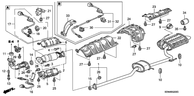
Alright, let's dive into the exhaust system of a 2006 Honda Accord. This article will break down a typical exhaust system diagram for this model, covering its components, function, and common issues. Understanding your exhaust system is crucial for several reasons. First, it's essential for proper emissions control, keeping your car legal and environmentally friendly. Second, it impacts fuel efficiency and engine performance. Third, diagnosing issues early can save you from costly repairs down the road. Finally, for the modders out there, understanding the system allows for informed decisions when upgrading components.
Key Specs and Main Parts
The 2006 Honda Accord came with a few engine options, most commonly the 2.4L inline-4 (K24A) and the 3.0L V6 (J30A). While the fundamental principles of their exhaust systems are the same, there are some differences in layout, particularly concerning the number of catalytic converters and exhaust manifolds.
Here's a breakdown of the main parts:
- Exhaust Manifold(s): This is where it all starts. Attached directly to the engine's cylinder head(s), the manifold collects exhaust gases from each cylinder. The 4-cylinder models have a single manifold, while the V6 engines have two, one for each bank of cylinders.
- Catalytic Converter(s): The catalytic converter is a critical emissions control device. It uses a catalyst (often platinum, palladium, and rhodium) to convert harmful pollutants (hydrocarbons, carbon monoxide, and nitrogen oxides) into less harmful substances like carbon dioxide, water, and nitrogen. The 4-cylinder model typically has one, while the V6 might have one or two depending on specific sub-model and emissions standards.
- Resonator: The resonator is essentially a tuned chamber designed to reduce specific frequencies of sound, helping to dampen and refine the exhaust note.
- Muffler: The muffler is the primary noise-reducing component of the exhaust system. It uses internal baffling and sound-absorbing materials to quiet the exhaust gases before they exit the vehicle.
- Piping: These are the various sections of tubing that connect the different components of the exhaust system. Typically made of steel, they are prone to rust over time, especially in areas with harsh winters.
- Oxygen Sensors (O2 Sensors): The O2 sensors are positioned before (upstream) and after (downstream) the catalytic converter(s). Upstream sensors measure the amount of oxygen in the exhaust gas, providing feedback to the engine control unit (ECU) to adjust the air-fuel mixture. Downstream sensors monitor the efficiency of the catalytic converter.
- Gaskets and Flanges: Gaskets are used at each joint in the exhaust system to provide a seal, preventing leaks. Flanges are the metal pieces that are bolted together to connect the different components.
Diagram Symbols
Understanding the symbols used in the diagram is key to interpreting it correctly.
- Solid Lines: Solid lines typically represent the actual exhaust piping. The thickness of the line may indicate the diameter of the pipe, but this is not always consistent, so check the legend.
- Dashed Lines: Dashed lines often represent vacuum lines or other related systems that are connected or interact with the exhaust system. These can include lines to the EGR (Exhaust Gas Recirculation) valve (if equipped) or to the fuel tank vent system.
- Boxes or Rectangles: These usually represent components like the catalytic converter, resonator, and muffler. Sometimes they will have labels inside indicating what they are.
- Circles or Ovals: These can represent sensors (like the O2 sensors) or other small components. Look for labels near the circles to identify them.
- Arrows: Arrows indicate the direction of flow of exhaust gases.
- Numbers and Labels: The diagram will be filled with numbers and labels that correspond to a parts list. This allows you to identify specific components and their part numbers.
- Colors (if present): In some diagrams, different colors might be used to differentiate between different materials or sections of the exhaust system. A legend should explain the meaning of each color.
How It Works
The exhaust system is designed to safely and efficiently remove exhaust gases from the engine, reduce harmful emissions, and minimize noise. Here's the basic flow:
- Exhaust gases are expelled from the engine's cylinders and enter the exhaust manifold(s).
- The gases then flow into the catalytic converter(s), where pollutants are converted into less harmful substances.
- From the catalytic converter, the gases travel through the resonator (if equipped), which helps to dampen certain frequencies of sound.
- Finally, the gases enter the muffler, where they are further quieted before being expelled into the atmosphere through the tailpipe.
- O2 sensors monitor the exhaust gas composition before and after the catalytic converter, providing data to the ECU to optimize engine performance and emissions control.
Real-World Use – Basic Troubleshooting Tips
Here are a few common issues and how the diagram can help:
- Exhaust Leak: A common problem is an exhaust leak, which can cause a noticeable hissing or roaring sound. Use the diagram to identify the location of gaskets and flanges, which are the most likely places for leaks to occur. Visually inspect these areas for signs of corrosion, cracks, or broken bolts. A soapy water solution sprayed on the suspected leak area can help pinpoint the location (look for bubbles).
- Catalytic Converter Failure: A failing catalytic converter can trigger a Check Engine Light (CEL) with codes like P0420 (Catalyst System Efficiency Below Threshold). The diagram will help you locate the catalytic converter and O2 sensors, allowing you to inspect them for damage or corrosion. You can also use a scan tool to monitor the O2 sensor readings and diagnose the converter's efficiency.
- Noisy Exhaust: Excessive exhaust noise can indicate a damaged muffler, resonator, or exhaust piping. The diagram will help you identify these components and inspect them for rust, holes, or cracks.
- O2 Sensor Problems: Faulty O2 sensors can cause a variety of engine performance issues, including poor fuel economy and rough idling. The diagram will show you the location of the O2 sensors, allowing you to inspect their wiring and connectors for damage. A scan tool can be used to monitor the sensor readings and diagnose any problems.
Safety
Working on the exhaust system can be dangerous due to the high temperatures involved. Here are some important safety precautions:
- Work on a Cool Exhaust: Never work on the exhaust system while it is hot. Allow the engine and exhaust system to cool completely before attempting any repairs.
- Wear Safety Glasses and Gloves: Protect your eyes and hands from debris and sharp edges.
- Use Proper Lifting Equipment: When lifting the vehicle, use a jack and jack stands to ensure it is safely supported. Never work under a vehicle supported only by a jack.
- Be Aware of Hot Surfaces: Even after the engine has cooled, some parts of the exhaust system may still retain heat. Use caution when handling these components.
- Avoid Breathing Exhaust Fumes: Work in a well-ventilated area to avoid inhaling exhaust fumes.
- Disconnect Battery: Disconnect the negative terminal of the battery before working on any electrical components, such as the O2 sensors.
The catalytic converter is a particularly risky component. It can remain extremely hot long after the engine is turned off. Exercise extreme caution when working near it.
We have a detailed 2006 Honda Accord exhaust system diagram available for download. This diagram will provide you with a visual reference for all the components mentioned in this article and can be invaluable for diagnosing and repairing exhaust system issues.