2006 Hyundai Sonata Fuse Box Diagram
Understanding your vehicle's electrical system is crucial for both routine maintenance and troubleshooting unexpected issues. The fuse box is the central nervous system of that electrical system, protecting sensitive components from overcurrents. This article provides a detailed explanation of the 2006 Hyundai Sonata fuse box diagram, empowering you to diagnose and resolve electrical problems with confidence. We'll cover the purpose of the diagram, key specifications, symbol interpretations, how the system works, real-world use cases, and essential safety precautions. And best of all, we have the full diagram available for download – link provided at the end.
Purpose of the Fuse Box Diagram
The fuse box diagram is essentially a roadmap of your car's electrical system. It shows the location of each fuse and relay, and more importantly, it specifies which electrical circuit each fuse protects. This is invaluable for several reasons:
- Troubleshooting Electrical Issues: When an electrical component fails (e.g., a light, the radio, or the air conditioning), the fuse box is often the first place to look. The diagram helps you quickly identify the fuse associated with that component.
- Replacing Blown Fuses: A blown fuse indicates an overcurrent condition. Replacing the fuse with one of the correct amperage rating will often restore functionality. The diagram shows you which amperage fuse to use.
- Understanding the Electrical System: Studying the diagram provides a broader understanding of how your car's electrical circuits are organized and interconnected.
- Modifications and Add-ons: If you're adding aftermarket electrical components (e.g., a new stereo system, auxiliary lights), the diagram can help you identify suitable power sources and ensure you're properly protecting the new circuit.
- Preventative Maintenance: Periodically checking the fuse box for corrosion or loose connections can prevent future electrical problems.
Key Specs and Main Parts
The 2006 Hyundai Sonata typically has two fuse boxes: one located in the interior (usually under the dashboard on the driver's side) and another in the engine compartment. Let's break down the key specifications and main parts:
- Location: As mentioned, interior and engine compartment. Knowing their exact location is the first step. Refer to your owner's manual for the precise location.
- Fuses: These are the sacrificial elements designed to break the circuit in case of an overcurrent. They come in various amperage ratings (measured in Amperes or "amps") and physical sizes/shapes. Common types include blade fuses (ATO/ATC), mini-blade fuses, and cartridge fuses. Never replace a fuse with a higher amperage fuse, as this can damage the wiring and components in the circuit.
- Relays: Relays are electromechanical switches that allow a low-current circuit to control a high-current circuit. They are used for components that require a significant amount of power, such as the headlights, starter motor, and fuel pump.
- Fuse Puller: A small plastic tool specifically designed for safely removing fuses. Most fuse boxes have one integrated into the cover.
- Fuse Box Cover: Protects the fuses and relays from dirt, moisture, and physical damage. The diagram is usually printed on the inside of the cover.
- Grounding Points: Although not directly part of the fuse box itself, the ground connections related to the circuits protected by the fuses are critical. A bad ground can cause all sorts of weird electrical problems.
Symbols - Interpreting the Fuse Box Diagram
Understanding the symbols used on the fuse box diagram is essential for proper diagnosis and repair. Here's a breakdown of common symbols:
- Lines: Lines represent electrical wires or circuits. Thicker lines may indicate circuits with higher current capacity.
- Colors: While not always explicitly indicated on the diagram, wire colors are often standardized. Knowing these standard colors can aid in tracing wires within the vehicle. For example, red wires often indicate a positive battery connection.
- Rectangles: Rectangles usually represent fuses. The amperage rating is typically printed inside or next to the rectangle.
- Squares or Rounded Rectangles: These often represent relays.
- Icons: Icons represent the electrical components protected by the fuse. Common icons include lights (headlights, taillights, interior lights), a radio, a cigarette lighter, a horn, an engine symbol (related to engine control circuits), and climate control symbols.
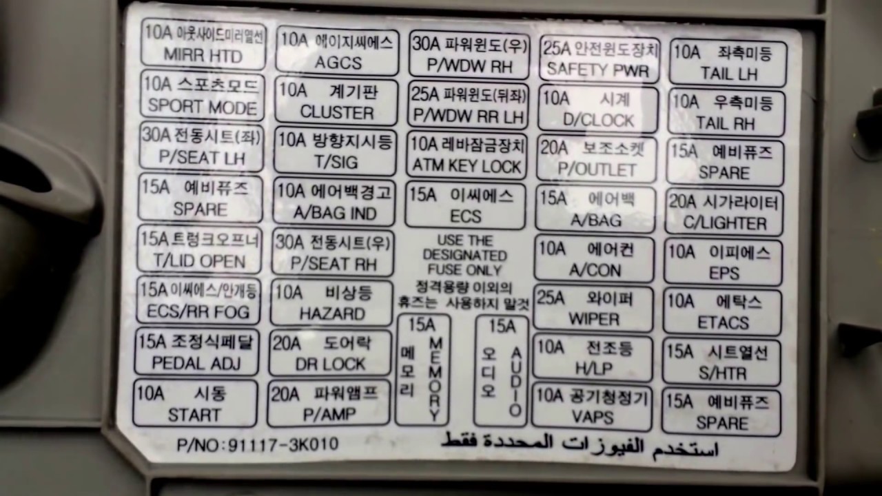
The diagram usually lists the fuse number, amperage, and a brief description of the circuit it protects. Pay close attention to these descriptions to accurately identify the fuse you need.
How It Works: The Electrical Protection System
The fuse box is a protective device integrated into your car's electrical system. The fundamental principle is simple: a fuse is a weak link in a circuit. It contains a thin wire or strip of metal designed to melt and break the circuit if the current exceeds a certain level.
Here's a simplified explanation:
- Normal Operation: When the circuit is operating normally, the current flows through the fuse without any interruption.
- Overcurrent Condition: If there's a short circuit (a low-resistance path to ground) or an overload (too many devices drawing current on the same circuit), the current exceeds the fuse's rating.
- Fuse Blows: The excessive current heats up the fuse element, causing it to melt and break the circuit.
- Circuit Protection: By breaking the circuit, the fuse prevents damage to the wiring, components, and potentially even a fire.
Relays work differently. They use a small electrical current to activate an electromagnet. This electromagnet pulls a switch, closing (or opening) a high-current circuit. Relays are used to protect smaller switches on the dash from carrying large currents.
Real-World Use: Basic Troubleshooting
Here's how to use the fuse box diagram for troubleshooting:
- Identify the Problem: Determine which electrical component is not working.
- Consult the Diagram: Locate the fuse box diagram (usually on the inside of the fuse box cover or in the owner's manual).
- Find the Fuse: Find the fuse that corresponds to the non-functioning component. The diagram will list the fuse number and a brief description.
- Inspect the Fuse: Remove the fuse using a fuse puller. Visually inspect the fuse. A blown fuse will have a broken filament or a blackened appearance. You can also use a multimeter set to continuity to test the fuse. A good fuse will show continuity (a reading close to zero ohms).
- Replace the Fuse: If the fuse is blown, replace it with a new fuse of the same amperage rating.
- Test the Component: Turn on the component to see if it now works.
- If the Fuse Blows Again: If the new fuse blows immediately, there is likely a short circuit in the wiring or the component itself. Further diagnosis is required. Do not keep replacing fuses without addressing the underlying problem.
Safety Precautions
Working with electrical systems can be dangerous. Here are some crucial safety precautions:
- Disconnect the Battery: Before working on the fuse box, disconnect the negative (-) battery cable to prevent accidental short circuits.
- Use Insulated Tools: Use insulated tools to avoid electrical shock.
- Replace with the Correct Amperage: Always replace a blown fuse with a fuse of the same amperage rating. Using a higher amperage fuse can damage the wiring and components in the circuit, and could even cause a fire.
- Avoid Water: Never work on the electrical system in wet conditions.
- High-Current Circuits: Be particularly cautious when working with fuses and relays related to high-current circuits such as the starter motor, alternator, and headlights.
Working on the SRS (Supplemental Restraint System, or airbags) circuits is extremely dangerous and should only be performed by a qualified technician. Accidental deployment of an airbag can cause serious injury.
Disclaimer: This article is for informational purposes only and should not be considered a substitute for professional advice. Always consult a qualified mechanic if you are unsure about any electrical repairs.
To further assist you in your repair, we have the complete 2006 Hyundai Sonata Fuse Box Diagram available for download. [Download Link Here - Placeholder]. Good luck with your repairs!