2006 Infiniti G35 Fuse Box Diagram
Alright folks, let's dive deep into the heart of your 2006 Infiniti G35's electrical system: the fuse box. Think of the fuse box as the central nervous system of your car's electrical circuits. Without it, everything from your headlights to your radio would be vulnerable to catastrophic shorts and overloads. This article will break down the 2006 Infiniti G35 fuse box diagram, equipping you with the knowledge to diagnose, troubleshoot, and even upgrade your car's electrical components with confidence. Knowing this information is invaluable for everything from basic maintenance to more advanced modifications.
Why Bother with the Fuse Box Diagram?
Why spend time learning about this seemingly mundane component? The answer is simple: it empowers you. A solid understanding of the fuse box diagram can save you time, money, and frustration in numerous scenarios. Whether you're replacing a blown fuse, diagnosing a malfunctioning component, or installing aftermarket accessories, the fuse box diagram is your roadmap. Without it, you're essentially working blind, potentially causing further damage or even electrical fires.
Specifically, you might need the diagram for:
- Troubleshooting Electrical Problems: Identifying the fuse associated with a specific circuit allows you to quickly isolate the source of the problem.
- Installing Aftermarket Accessories: Tapping into existing circuits for accessories like amplifiers, lights, or alarms requires knowing which fuse controls which circuit.
- Performing Preventative Maintenance: Checking fuses regularly can help identify potential problems before they escalate.
- Understanding Your Car's Electrical System: Gaining a deeper understanding of how your car's electrical system is laid out can improve your overall knowledge of automotive technology.
Key Specs and Main Parts
The 2006 Infiniti G35 typically has two main fuse box locations:
- Interior Fuse Box: Located inside the cabin, usually under the dashboard on the driver's side or behind the glove compartment on the passenger side. This box primarily houses fuses for interior components like the radio, lights, power windows, and climate control.
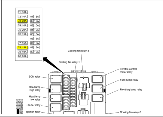
- Engine Compartment Fuse Box: Located under the hood, usually near the battery or the engine control module (ECM). This box contains fuses for engine management systems, headlights, horn, and other critical engine-related components.
Key components within the fuse boxes include:
- Fuses: The heart of the system, fuses are designed to break the circuit when the current exceeds a safe level, preventing damage to electrical components. They are rated in amperes (amps), which indicates the maximum current they can handle.
- Relays: These are electromechanical switches that allow a low-current circuit to control a high-current circuit. For example, a low-current signal from the headlight switch activates a relay that switches on the high-current headlights.
- Fuse Puller: A small plastic tool used to safely remove fuses from the fuse box without damaging them or the surrounding components.
- Spare Fuses: Many fuse boxes include a selection of spare fuses of various amperage ratings. Always keep a selection of spare fuses on hand.
Decoding the Symbols: Lines, Colors, and Icons
The fuse box diagram is a schematic representation of the electrical circuits, utilizing specific symbols and conventions to convey information. Understanding these symbols is crucial for interpreting the diagram correctly.
- Lines: Solid lines represent electrical wires connecting different components. The thickness of the line doesn't necessarily indicate the wire's gauge.
- Colors: Wire colors are often indicated on the diagram using abbreviations (e.g., "R" for red, "BLU" for blue, "BLK" for black). These colors help you identify the correct wire in the actual harness.
- Icons: Standardized icons represent various electrical components, such as:
 A rectangle with a zigzag line represents a fuse.
 A square with a coil inside represents a relay.
 A series of horizontal lines decreasing in length represents a ground connection.
- Numbers: Each fuse and relay is typically assigned a number or identifier on the diagram, which corresponds to a physical location in the fuse box.
The diagram will often include a legend or key that explains the meaning of each symbol and abbreviation used.
How It Works: A Simple Circuit Example
Let's illustrate how a fuse protects a simple circuit, like the one for your interior lights. Imagine a circuit consisting of the battery, a fuse, a switch, and the interior light bulb.
- Power flows from the battery, through the fuse, and to the switch.
- When the switch is turned on, it completes the circuit, allowing current to flow to the light bulb, causing it to illuminate.
- If a short circuit occurs (e.g., a wire insulation breaks and the wire touches the car's chassis), the current will surge dramatically.
- This surge of current heats the fuse element (a thin strip of metal inside the fuse) until it melts, breaking the circuit and stopping the flow of current.
- The blown fuse prevents the short circuit from damaging the wiring, the switch, or the light bulb itself.
The amperage rating of the fuse is crucial. Using a fuse with a higher amperage rating than specified can allow excessive current to flow in the event of a short, potentially causing damage or even a fire. Using a fuse with a lower amperage rating will cause it to blow prematurely, interrupting the circuit even under normal operating conditions.
Real-World Use: Basic Troubleshooting Tips
Here are a few practical tips for using the fuse box diagram to troubleshoot electrical problems:
- Identify the Symptom: Determine which component is malfunctioning. For example, "The headlights don't work."
- Consult the Diagram: Locate the fuse or relay associated with the malfunctioning component in the fuse box diagram.
- Inspect the Fuse: Remove the fuse using a fuse puller and visually inspect it. Look for a broken filament inside the fuse. A multimeter can also be used to test the fuse for continuity.
- Replace the Fuse: If the fuse is blown, replace it with a new fuse of the exact same amperage rating.
- Test the Circuit: After replacing the fuse, test the circuit to see if the problem is resolved. If the new fuse blows immediately, there is likely a short circuit in the wiring or the component itself. Further diagnosis is required.
- Check the Relays: Relays can also fail. If the fuse is good but the component still doesn't work, try swapping the relay with a known good relay of the same type.
Safety First: Highlighting Risky Components
Working with automotive electrical systems can be dangerous if proper precautions are not taken. Always disconnect the negative battery terminal before working on any electrical components. This will prevent accidental short circuits and potential electrical shocks.
Be particularly careful when working with the following:
- Airbag System: Fuses and wiring related to the airbag system are typically marked with a warning label. Mishandling these components can cause accidental airbag deployment, which can be dangerous.
- Fuel Pump: The fuel pump circuit carries a relatively high current. Short circuits in this circuit can create a fire hazard.
- Engine Control Module (ECM): The ECM is a sensitive electronic component. Incorrect wiring or voltage can damage the ECM.
If you are not comfortable working with electrical components, it is always best to consult a qualified mechanic. Incorrect wiring or troubleshooting can lead to costly repairs or even dangerous situations. Always double check your work, and never exceed the specified amperage rating of a fuse.
We have the complete 2006 Infiniti G35 fuse box diagram file available for download. This diagram will be invaluable for any electrical work you undertake on your vehicle. Download it and keep it handy – you'll thank yourself later!