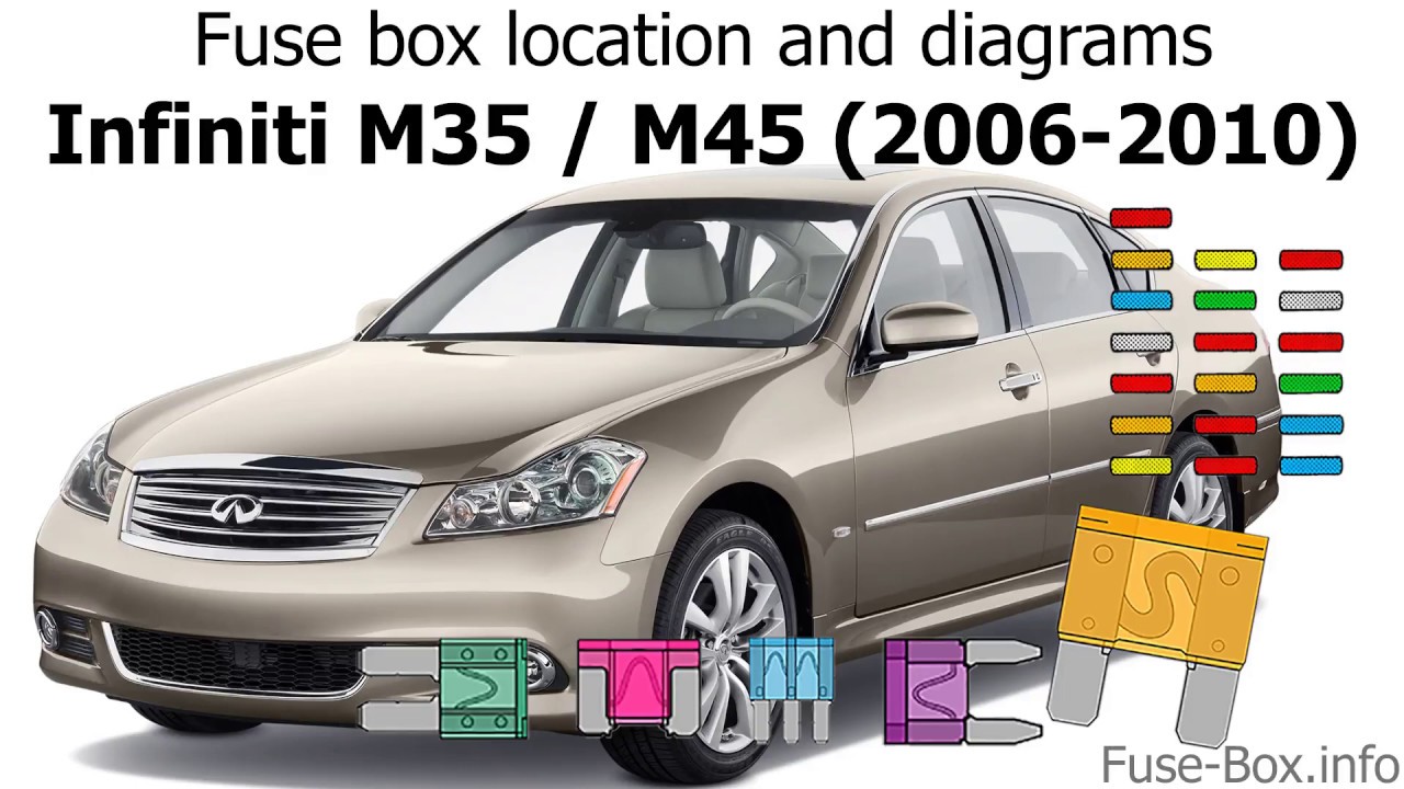
2006 Infiniti M35 Fuse Box Diagram
Understanding your vehicle's electrical system is crucial for effective maintenance and repair. One of the most vital tools in this endeavor is the fuse box diagram. For owners and enthusiasts of the 2006 Infiniti M35, having a clear understanding of the fuse box layout is essential. This article serves as a comprehensive guide to the 2006 Infiniti M35 fuse box diagram, covering its purpose, key components, symbolism, operation, and practical usage.
Purpose of the Fuse Box Diagram
The fuse box diagram is essentially a roadmap of your car's electrical protection system. Its primary purpose is to identify the location and function of each fuse and relay within the vehicle. Understanding this diagram allows you to:
- Quickly Diagnose Electrical Issues: When an electrical component malfunctions, the first step is often to check the corresponding fuse. The diagram tells you which fuse to examine.
- Perform Repairs Safely: Knowing which fuse controls which circuit allows you to isolate and de-energize specific components before working on them, minimizing the risk of electrical shock or damage.
- Install Aftermarket Accessories: If you're adding things like new lights or an upgraded stereo system, the fuse box diagram will help you find suitable power sources and protect your new equipment with appropriate fuses.
- General Understanding: Even if you're not actively troubleshooting, understanding the layout of the electrical system gives you a better overall grasp of how your car works.
Think of it as the electrical equivalent of a plumbing diagram for your house. Without it, you're poking around in the dark. With it, you have a clear map to guide you.
Key Specs and Main Parts of the 2006 Infiniti M35 Fuse Box
The 2006 Infiniti M35 typically has two main fuse box locations:
- Interior Fuse Box: Located under the dashboard, usually on the driver's side. This box generally houses fuses for interior components such as lights, the radio, the climate control system, and the instrument panel.
- Engine Compartment Fuse Box: Situated in the engine bay, this box protects circuits related to the engine, transmission, and other critical systems. It contains fuses for the fuel pump, ignition system, cooling fans, and headlights, among others.
Inside each fuse box, you'll find:
- Fuses: These are the sacrificial components that protect the circuit. They are rated in amperes (amps), indicating the maximum current they can handle before blowing (breaking the circuit).
- Relays: Relays are electromechanical switches that allow a low-current circuit to control a high-current circuit. They're used to switch on components like headlights or the fuel pump, which require a large amount of power.
- Fuse Puller: A small plastic tool designed to safely remove fuses without damaging them.
The specific amperage ratings of the fuses are critical. Replacing a blown fuse with one of a higher amperage rating can be extremely dangerous, potentially causing a fire. Always use the correct replacement fuse as indicated on the fuse box diagram or the fuse box cover.
Understanding Fuse Box Symbols
Fuse box diagrams use symbols to represent different components and their functions. Here’s a breakdown of common symbols you might encounter:
- Solid Lines: These represent electrical wires or circuits. The thickness of the line doesn't usually denote wire gauge in these diagrams, but it highlights important traces.
- Colors: While not always present on printed diagrams, color-coded wiring diagrams often indicate the function of the wire. For example, red might indicate a positive (+) power supply, while black represents ground (-).
- Fuse Symbol: Usually represented by a zigzag line within a rectangle.
- Relay Symbol: Typically shown as a coil with a switch. The coil represents the electromagnet that activates the switch.
- Component Icons: Simple icons represent various components, like a headlight symbol for the headlight circuit or a fan icon for the radiator fan.
The diagram will also contain text labels identifying each fuse or relay and its corresponding function (e.g., "Headlight - Right," "Fuel Pump Relay"). Pay close attention to these labels.
How It Works: The Electrical Circuit Protection System
The fuse box acts as the central control and protection hub for your car's electrical system. Each circuit is designed to power a specific component or group of components. A fuse is placed in series within each circuit. If an overcurrent condition occurs (e.g., a short circuit), the fuse will melt (blow), breaking the circuit and preventing damage to the component and the wiring.
The Ohm's Law, which states that Voltage (V) = Current (I) * Resistance (R), is fundamental to understanding how fuses work. When resistance in a circuit drops drastically (like in a short), the current increases dramatically. The fuse, designed with a specific resistance and melting point, responds to this increase by overheating and breaking the connection, preventing further current flow.
Relays, on the other hand, act as remote switches. A low-current signal from the control unit (like the ECM – Engine Control Module) activates the relay's coil, which in turn closes a high-current circuit, powering the component. This allows the ECM to control high-power devices without being subjected to the full current load.
Real-World Use: Basic Troubleshooting Tips
Here's a scenario: your headlights suddenly stop working.
- Consult the Fuse Box Diagram: Locate the diagram for the engine compartment fuse box.
- Identify the Headlight Fuse(s): Find the fuse(s) labeled for the headlights (there might be separate fuses for left and right headlights).
- Inspect the Fuse(s): Remove the fuse(s) using the fuse puller. Examine the fuse element. If it's broken or blackened, the fuse is blown.
- Replace the Fuse: Replace the blown fuse with a new fuse of the exact same amperage rating.
- Test the Headlights: Turn on the headlights to see if they now function.
If the new fuse blows immediately, there's likely a short circuit in the headlight wiring or within the headlight assembly itself. Further troubleshooting is required. You might need a multimeter to check for continuity (a short) in the circuit.
Important Notes: If a fuse blows repeatedly, do NOT simply replace it with a higher-rated fuse. This is a fire hazard! Diagnose and repair the underlying problem that's causing the overcurrent condition. If you are not comfortable diagnosing the electrical issue, consult a qualified mechanic.
Safety Considerations
Working with automotive electrical systems involves inherent risks. Here are some safety precautions to keep in mind:
- Disconnect the Battery: Before working on any electrical component, disconnect the negative (-) battery cable to prevent accidental short circuits.
- Use Proper Tools: Use insulated tools designed for automotive electrical work.
- Avoid Working in Wet Conditions: Water conducts electricity, increasing the risk of electric shock.
- Be Cautious Around High-Voltage Components: The ignition system, particularly the ignition coils, can generate high-voltage electricity even with the battery disconnected. Handle these components with extreme care.
- Never Bypass a Fuse: Bypassing a fuse with a wire or other conductive material is extremely dangerous and can cause a fire.
Specifically, components like the ECM (Engine Control Module) and the ABS (Anti-lock Braking System) module are sensitive to voltage spikes and can be damaged by improper electrical work. Always follow the manufacturer's instructions and consult a qualified technician if you are unsure.
Having access to the correct 2006 Infiniti M35 fuse box diagram is key to safely and effectively maintaining your car’s electrical system. We have the file available for you to download. With this resource and the knowledge in this article, you’ll be well-equipped to tackle basic electrical troubleshooting and repairs.