2006 Jeep Commander Fuse Box Diagram
The 2006 Jeep Commander is a versatile SUV, but like any vehicle, it relies on a complex electrical system. Understanding that system begins with understanding its fuse box diagram. This isn't just a piece of paper; it's your roadmap to diagnosing and resolving electrical issues, planning modifications, and gaining a deeper understanding of your Commander's inner workings. Whether you're troubleshooting a blown tail light, installing a new aftermarket accessory, or simply want to know how your Jeep's electrical components are protected, mastering the fuse box diagram is crucial.
Purpose of the 2006 Jeep Commander Fuse Box Diagram
The fuse box diagram serves several vital purposes:
- Troubleshooting Electrical Issues: When an electrical component fails, the first step is often checking the corresponding fuse. The diagram tells you exactly which fuse to inspect, saving you time and frustration.
- Installing Aftermarket Accessories: Adding new lights, a sound system, or other electrical modifications requires tapping into the existing electrical system. The diagram helps you identify appropriate circuits for power and ground connections.
- Understanding Circuit Protection: The diagram provides insight into how different circuits are protected by fuses or relays. This knowledge is essential for preventing overloads and potential electrical fires.
- Replacing Fuses Correctly: Using the wrong amperage fuse can cause further damage or create a safety hazard. The diagram ensures you're using the correct fuse for each circuit.
- General Vehicle Knowledge: Studying the fuse box diagram deepens your understanding of your Jeep Commander's electrical architecture.
Key Specs and Main Parts
The 2006 Jeep Commander typically features two main fuse box locations:
- Power Distribution Center (PDC): Located in the engine compartment, this box houses fuses and relays for high-current circuits like the starter motor, alternator, and main lighting systems. It's the primary electrical hub for the vehicle.
- Junction Block: Situated inside the cabin, usually under the dashboard or in the glove compartment, this box contains fuses for lower-current circuits like the radio, interior lights, and power windows.
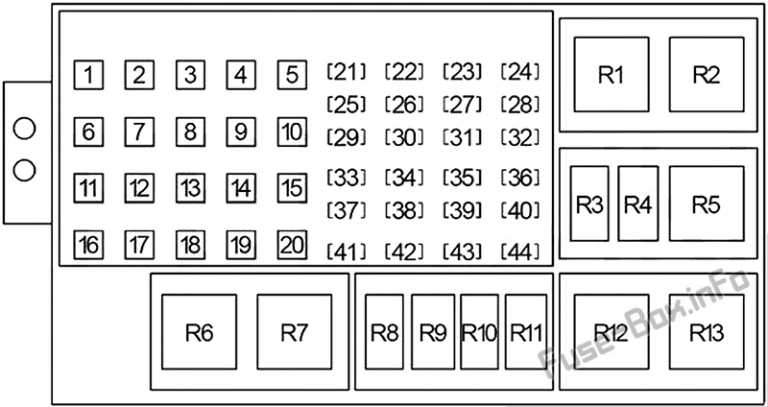
The diagram for each location shows the physical layout of the fuses and relays, with each component labeled with a number or code. Beside the layout, there's usually a legend listing each number or code and its corresponding circuit. Here are some key terms to understand:
- Fuse: A safety device containing a metal strip that melts and breaks the circuit if the current exceeds a certain level, protecting the wiring and components from damage. Fuses are rated in amperes (amps), indicating the amount of current they can handle.
- Relay: An electrically operated switch that allows a low-current circuit to control a high-current circuit. Relays are used for components that draw a lot of power, like headlights or the fuel pump.
- Circuit: A complete path for electrical current to flow from the power source (battery) to a load (e.g., a light bulb) and back to the ground.
- Amperage (Amps): A measure of the electrical current flowing through a circuit.
- Voltage (Volts): A measure of the electrical potential difference, or the "pressure" that drives the current through a circuit. The 2006 Jeep Commander operates on a 12-volt system.
Symbols and Legend Explanation
The fuse box diagram uses a variety of symbols, lines, and colors to convey information efficiently. Here's a breakdown of common symbols:
- Lines: Solid lines typically represent wires connecting components. Dotted or dashed lines might indicate ground connections or signal wires.
- Colors: Wire colors are often indicated on the diagram using abbreviations (e.g., RD for Red, BL for Blue, BK for Black). These color codes are helpful when tracing wires within the vehicle.
- Fuse Symbols: Fuses are generally represented by a small rectangle or a symbol resembling a stylized fuse.
- Relay Symbols: Relays are often depicted as a square or rectangle with internal components indicating the coil and switch contacts.
- Component Icons: The diagram may include simplified icons representing the components protected by each fuse or relay (e.g., a light bulb for the headlight circuit, a speaker for the radio circuit).
The legend is crucial. It's a table or list that correlates each number or code on the diagram with the corresponding circuit description and fuse amperage rating. Without the legend, the diagram is practically useless. For example, a legend entry might read: "F32 - Headlight (Low Beam) - 15A". This means fuse number 32 protects the low beam headlights and has a rating of 15 amps.
How It Works: The Electrical Flow
Understanding how the electrical system works, and how the fuse box fits in, is key to effective troubleshooting. Electricity flows from the battery, through the wiring harness, to various components. Each component requires a specific amount of current to operate. Fuses are strategically placed in these circuits to protect them from overcurrent situations.
If a component malfunctions or a short circuit occurs (e.g., a wire chafes against the chassis and creates a direct path to ground), the current draw increases dramatically. This excessive current flow heats up the fuse element, causing it to melt and break the circuit. This interruption prevents further damage to the wiring and components. Relays act as remote-controlled switches. A low-current signal activates the relay, which then closes a high-current circuit to power a component like a starter motor or a set of auxiliary lights.
The Power Distribution Center manages and distributes power to high-demand systems. Inside the cabin, the Junction Block handles lower-power circuits related to interior comfort and convenience.
Real-World Use: Basic Troubleshooting Tips
Here's how to use the fuse box diagram to troubleshoot common electrical problems:
- Identify the Problem: Determine which component is not working (e.g., the radio, a tail light, the power windows).
- Consult the Diagram: Locate the fuse box diagram for the appropriate location (PDC or Junction Block).
- Find the Correct Fuse: Using the diagram and legend, identify the fuse that protects the malfunctioning component's circuit.
- Inspect the Fuse: Carefully remove the fuse and inspect it. A blown fuse will have a broken or melted element. A good fuse will have an intact element.
- Replace the Fuse: If the fuse is blown, replace it with a new fuse of the same amperage rating. Using a higher amperage fuse can overload the circuit and create a fire hazard.
- Test the Component: After replacing the fuse, test the component to see if it's working again.
- If the Fuse Blows Again: If the new fuse blows immediately or shortly after replacement, it indicates a more serious problem, such as a short circuit in the wiring or a faulty component. Further diagnosis and repair by a qualified mechanic may be necessary.
When removing and installing fuses, use a fuse puller tool. This will prevent damage to the fuse box and make the process easier.
Safety Precautions
Working with electrical systems can be dangerous. Always observe the following safety precautions:
- Disconnect the Battery: Before working on the electrical system, disconnect the negative terminal of the battery to prevent accidental shorts and electric shocks.
- Use Insulated Tools: Use tools with insulated handles to protect yourself from electric shock.
- Never Replace a Fuse with a Higher Amperage: Doing so can overload the circuit and create a fire hazard. Always use the correct amperage fuse as specified in the diagram.
- Avoid Working in Wet Conditions: Water can conduct electricity and increase the risk of electric shock.
- Be Aware of High-Current Components: Components like the starter motor and alternator carry high currents. Be extremely cautious when working around these components.
- Do not work on the airbag system unless properly trained and equipped. The airbag system is a potentially dangerous system that can cause serious injury if handled improperly. This system has its own dedicated fuse that needs to be respected.
The Power Distribution Center contains relays and fuses controlling systems like the fuel pump and ignition. Tampering with these circuits can cause the engine to stall or prevent it from starting, potentially leading to a dangerous situation if you're driving. Exercise extreme caution when working in this area.
Understanding the 2006 Jeep Commander's fuse box diagram empowers you to diagnose and resolve electrical issues effectively. Remember to prioritize safety and consult a professional mechanic when dealing with complex problems or high-current circuits. With a little knowledge and the right tools, you can keep your Jeep's electrical system running smoothly.
We have the full 2006 Jeep Commander fuse box diagram available for download. It includes detailed layouts and legends for both the Power Distribution Center and the Junction Block. You can download it here: [Insert Download Link Here, or Instructions for access]