2006 Jeep Grand Cherokee Interior Fuse Box Diagram
Let's dive into the 2006 Jeep Grand Cherokee's interior fuse box diagram. Understanding this diagram is crucial for anyone tackling electrical repairs, modifications, or simply trying to diagnose an issue in their WK Grand Cherokee. Think of it as the Rosetta Stone for your Jeep's electrical system. Without it, you're fumbling in the dark. We're here to shed some light, providing you with the knowledge to confidently navigate this sometimes-intimidating area. Whether you're replacing a blown fuse, adding aftermarket accessories, or tracing a short circuit, a clear understanding of the fuse box diagram is indispensable. And, importantly, we have the full, downloadable diagram ready for you.
Purpose and Importance
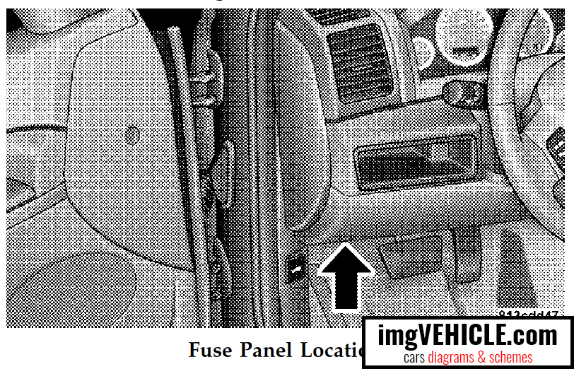
The interior fuse box, typically located in the driver's side footwell, houses an array of fuses and relays that protect various electrical circuits within your 2006 Grand Cherokee. These circuits power everything from the radio and interior lights to vital systems like the power windows and door locks. The fuse box diagram is essentially a map that identifies each fuse and relay, along with its corresponding circuit.
Why is this so important? Imagine your radio suddenly stops working. Without the diagram, you'd be forced to test each fuse individually, a tedious and time-consuming process. With the diagram, you can quickly locate the fuse responsible for the radio and determine if it's blown. This applies to countless other electrical issues. Moreover, if you're planning to add aftermarket accessories, like a new sound system or auxiliary lighting, understanding the fuse box diagram is critical for safely tapping into the appropriate circuits and preventing overload. It's all about precision and avoiding the dreaded electrical fire.
Key Specs and Main Parts of the Fuse Box
The interior fuse box in the 2006 Grand Cherokee typically uses standard blade-type fuses. These fuses come in various amperage ratings, indicated by their color. Common amperage ratings you'll encounter include 5A, 10A, 15A, 20A, 25A, and 30A. It's crucial to replace a blown fuse with one of the exact same amperage rating. Using a fuse with a higher amperage rating can overload the circuit and potentially cause damage or even a fire. Lower rating fuses won't work properly and will fail as well.
Besides fuses, you'll also find relays in the fuse box. Relays are electromechanical switches that control high-current circuits using a low-current signal. For example, the fuel pump relay allows the relatively small current from the ignition switch to activate the fuel pump, which requires a much higher current. The main parts you need to identify from the diagram are:
- Fuses: These are the sacrificial elements that protect individual circuits from overcurrent. They are designed to blow (interrupt the circuit) when the current exceeds their rated amperage.
- Relays: Electromechanical switches that control high-current circuits. They are often used to control components like the fuel pump, starter motor, and headlights.
- Fuse Box Housing: The physical container that houses the fuses and relays. It's typically made of plastic and provides a secure and organized location for the electrical components.
- Terminal Connectors: These connectors provide the electrical connection between the fuse box and the wiring harness. They are crucial for ensuring a reliable electrical connection.
Understanding the Symbols and Diagram Conventions
Fuse box diagrams often use a combination of lines, colors, and icons to represent the different electrical components and circuits. Let's break down some common symbols:
- Solid Lines: Usually indicate a direct electrical connection between two components.
- Dashed Lines: May indicate a ground connection or a less critical connection. Consult the specific diagram for clarification.
- Colors: Fuse colors denote the amperage rating, as mentioned earlier. The diagram will often have a color key to help you identify the correct fuse.
- Icons: Icons are used to represent specific components, such as a headlight, radio, or power window motor. The diagram should include a legend that explains the meaning of each icon.
Furthermore, diagrams are laid out for clear reading. Read from left to right, top to bottom. Grouped fuses and relays can represent a functional cluster of circuits like door locks or interior lights. Careful observation of the diagram's legend and labels is key.
How It Works: The Circuit Protection Mechanism
Each fuse protects a specific electrical circuit by interrupting the flow of current when it exceeds the fuse's rated amperage. This is achieved through a thin wire or strip of metal inside the fuse that melts when exposed to excessive current. This melting action breaks the circuit, preventing damage to the components connected to that circuit.
When a circuit experiences a short circuit (an unintended path of low resistance), the current flow increases dramatically. This sudden surge of current causes the fuse to blow, protecting the wiring and components from overheating and potentially causing a fire. Similarly, an overload (too many devices drawing power from the same circuit) can also cause a fuse to blow.
Relays, on the other hand, act as remotely controlled switches. A small current is applied to the relay's coil, which creates a magnetic field that pulls a contact closed, completing a high-current circuit. This allows a low-current signal, such as a switch on the dashboard, to control a high-current device, such as the headlights.
Real-World Use and Troubleshooting Tips
Let's get practical. Here are some basic troubleshooting tips using the fuse box diagram:
- Symptom Identification: First, identify the specific electrical problem you're experiencing. For example, "the windshield wipers don't work."
- Diagram Consultation: Consult the fuse box diagram to identify the fuse and/or relay responsible for the windshield wipers. Refer to the legend and icons to accurately locate the correct component.
- Fuse Inspection: Visually inspect the fuse. Look for a broken filament inside the fuse. If the filament is broken, the fuse is blown and needs to be replaced. Even if it looks OK, use a multimeter to test for continuity across the fuse. A blown fuse will show no continuity.
- Relay Testing: Testing relays is a bit more complex and often requires a multimeter and a basic understanding of relay operation. You can typically test a relay by applying a voltage to the coil terminals and checking for continuity between the switch terminals. There are also relay testers available.
- Replacement: Replace the blown fuse with a new fuse of the exact same amperage rating. If the fuse blows again immediately after replacement, there is likely a short circuit in the wiring or a faulty component in that circuit. Further investigation is needed.
Safety Considerations
Working with electrical systems can be dangerous if proper precautions aren't taken. Here are some key safety points:
- Disconnect the Battery: Always disconnect the negative terminal of the battery before working on the electrical system. This will prevent accidental short circuits and potential electric shock.
- Avoid Water: Never work on the electrical system in wet conditions. Water can conduct electricity and create a serious shock hazard.
- Use Proper Tools: Use insulated tools designed for electrical work. This will help prevent accidental short circuits and protect you from electric shock.
- High-Current Components: Be especially careful when working with high-current components, such as the starter motor, alternator, and battery. These components can deliver a powerful electric shock. Always disconnect the battery before working on these components.
- Airbag Circuits: Be extremely cautious when working near airbag circuits. Accidental activation of an airbag can cause serious injury. If you are unsure about working near airbag circuits, consult a qualified technician.
It's crucial to emphasize the risk associated with airbag circuits. Improper handling can result in accidental deployment, causing severe injuries. If you are at all uncomfortable or unfamiliar with working on these systems, seek professional assistance. When disconnecting the battery to work on electrical components, be aware that you may need to reset electronic devices after reconnecting the power.
Remember, your safety is paramount. If you're unsure about any aspect of the repair, don't hesitate to consult a qualified mechanic.
Now that you're armed with this information, you're better equipped to tackle basic electrical troubleshooting on your 2006 Jeep Grand Cherokee. Remember to always prioritize safety and consult the full fuse box diagram for accurate information. The diagram is a crucial resource, and we have it available for you to download. Having it on hand will save you time, money, and potential headaches down the road. Good luck!