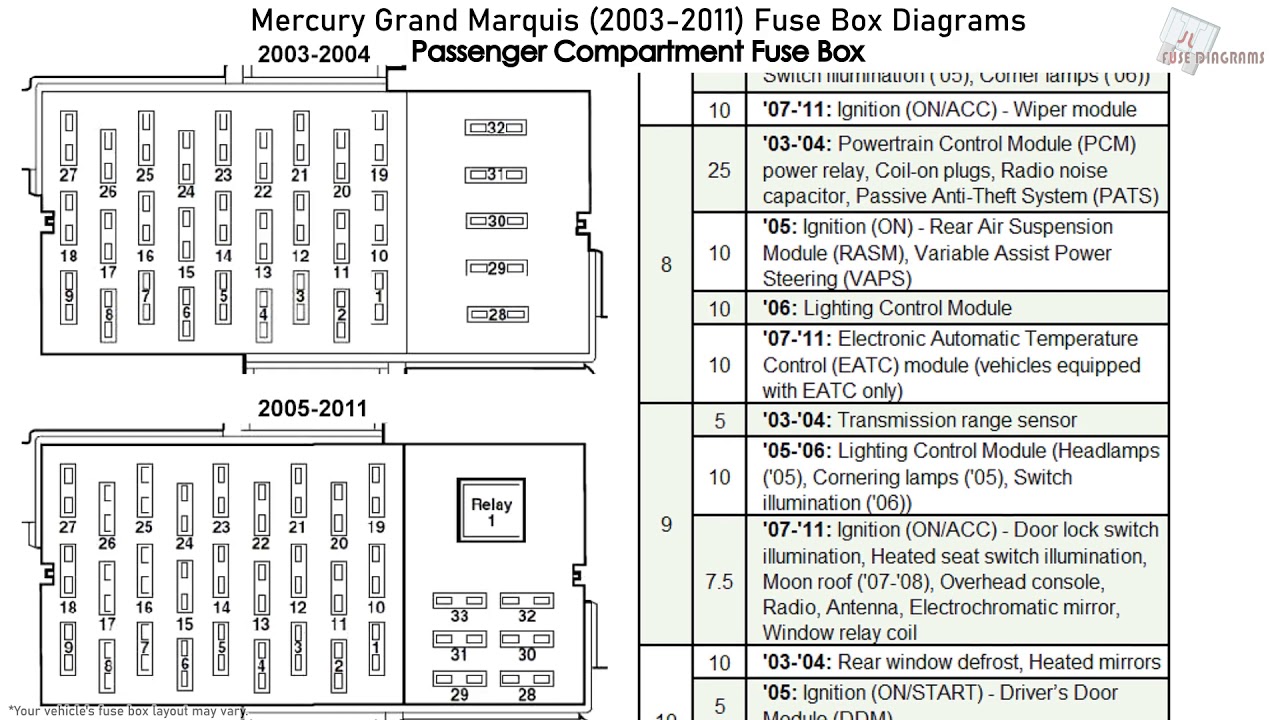
2006 Mercury Grand Marquis Fuse Box Diagram
Let's dive into the fuse box diagram for the 2006 Mercury Grand Marquis. Understanding this diagram is crucial for anyone tackling electrical repairs, troubleshooting issues, or even planning modifications on their car. Think of it as the Rosetta Stone for your car's electrical system. It allows you to understand the architecture of the electrical circuits so you can perform maintenance and repairs with confidence.
Why Bother with the Fuse Box Diagram?
A fuse box diagram is more than just a piece of paper; it's your guide to understanding your vehicle's electrical network. It allows you to perform a variety of essential tasks:
- Troubleshooting Electrical Problems: Identify which fuse controls a specific component. This allows you to quickly diagnose a faulty fuse or circuit.
- Locating Circuits: Pinpoint the exact location of a particular circuit within the car's wiring.
- Planning Modifications: Determine the power source and wiring route for new electrical components like aftermarket lights, audio systems, or security systems.
- Understanding the Car's Electrical System: Gain a deeper understanding of how different parts of the car are connected and powered.
Without the fuse box diagram, you're essentially working in the dark, risking misdiagnosis, accidental damage, and potentially even electrical fires.
Key Specs and Main Parts
The 2006 Mercury Grand Marquis typically has two fuse boxes. One is located under the hood, in the engine compartment, usually near the battery. The other is located inside the passenger cabin, often on the driver's side, behind a panel beneath the dashboard. Some models may have a third auxiliary fuse box, though this is less common.
Each fuse box contains a multitude of fuses and relays. Here's a breakdown of the key components:
- Fuses: These are safety devices designed to protect circuits from overcurrent. They contain a thin wire that melts and breaks the circuit if too much current flows through it. Fuses are rated in amperes (amps), indicating the maximum current they can handle before blowing.
- Relays: Relays are electromagnetic switches that allow a low-current circuit to control a high-current circuit. They are used to switch components like headlights, horns, and fuel pumps, which require a lot of power.
- Circuit Breakers: Similar to fuses, circuit breakers protect circuits from overcurrent. However, instead of melting, they trip and can be reset. Circuit breakers are less common in automotive applications than fuses.
- Fuse Puller: A small plastic tool used to safely remove fuses from the fuse box.
The fuse box diagram itself typically consists of a layout showing the physical locations of the fuses and relays, along with a legend that identifies the function of each fuse and relay. You'll find labels like "Headlamp," "Fuel Pump," "ABS," etc., indicating which component each fuse or relay protects or controls.
Understanding the Symbols: Lines, Colors, and Icons
Fuse box diagrams use various symbols to represent different components and connections. Here's a guide to decoding those symbols:
- Solid Lines: Represent wires connecting components. Heavier lines might indicate thicker wires for higher current circuits.
- Dotted Lines: Often used to represent ground connections.
- Colors: Wire colors are often indicated on the diagram (e.g., "RD" for Red, "BLU" for Blue, "BLK" for Black). These colors help you trace wires in the vehicle.
- Fuse Symbols: Fuses are typically represented by a rectangular or box-like symbol. The ampere rating (e.g., "15A") is usually indicated next to the symbol.
- Relay Symbols: Relays are often depicted as a square with a coil symbol inside.
- Ground Symbol: The ground connection is usually represented by a symbol resembling an upside-down triangle or a series of lines getting progressively shorter.
The diagram should have a key or legend that explains all the symbols and abbreviations used. Make sure to refer to this legend carefully.
How It Works: The Electrical Circuit
To truly understand the fuse box diagram, you need to grasp the basics of an electrical circuit. A circuit is a closed loop that allows electricity to flow from a power source (the battery) to a component (e.g., a light bulb) and back to the power source. The circuit consists of:
- Power Source: The car battery (typically 12 volts).
- Wiring: Conducts the electrical current.
- Switch: Controls the flow of current (e.g., a headlight switch).
- Load: The component that uses the electrical energy (e.g., a light bulb, a motor).
- Ground: A connection to the car's chassis, providing a return path for the current.
The fuse is inserted into the circuit to protect it from overcurrent. If there is a short circuit (an unintended low-resistance path to ground) or if a component draws too much current, the fuse will blow, breaking the circuit and preventing damage to the wiring or components.
Real-World Use: Basic Troubleshooting Tips
Here's how you can use the fuse box diagram to troubleshoot common electrical problems:
- Symptom Identification: First, identify the specific component that is not working (e.g., the windshield wipers, the radio, the cigarette lighter).
- Fuse Location: Consult the fuse box diagram to find the fuse that controls that component. The diagram will tell you the location of the fuse within the fuse box.
- Fuse Inspection: Use the fuse puller to carefully remove the fuse and inspect it. A blown fuse will have a broken filament (the thin wire inside).
- Fuse Replacement: If the fuse is blown, replace it with a new fuse of the same ampere rating. Never use a fuse with a higher rating, as this can damage the circuit.
- Test: After replacing the fuse, test the component to see if it now works.
- Persistent Blowing: If the fuse blows again immediately after replacement, there is likely a short circuit in the wiring or a faulty component. This requires further investigation and may necessitate a qualified mechanic.
Important Note: Before replacing any fuse, make sure the ignition is switched off and the component in question is turned off. This will prevent accidental shorts.
Safety: Highlighting Risky Components
Working with electrical systems can be dangerous. Here are some important safety precautions:
- Battery Disconnect: Before working on any electrical system, disconnect the negative terminal of the battery to prevent accidental shorts and shocks.
- Avoid Water: Never work on electrical systems in wet conditions.
- Proper Tools: Use insulated tools to avoid shocks.
- Fuse Rating: Always replace a fuse with one of the same ampere rating. Using a higher-rated fuse can cause serious damage or even a fire.
- Airbag Circuits: Be extremely careful when working near airbag circuits. Accidental triggering of an airbag can cause serious injury. If you are unsure about how to handle airbag circuits, consult a qualified mechanic.
- Capacitors: Some components, particularly in audio systems, contain capacitors that can store a charge even after the battery is disconnected. Be careful when handling these components.
Electrical systems, while not always immediately dangerous, require proper respect and safety protocols. When dealing with electrical issues in your car, safety must be your top priority.
Fuse box diagrams are indispensable tools for anyone undertaking automotive electrical work. By understanding the diagram, you can confidently diagnose problems, plan modifications, and maintain your vehicle's electrical system. With knowledge of the electrical components, schematics, and safety measures you are ready to repair electrical issues.
We have the 2006 Mercury Grand Marquis Fuse Box Diagram file available for download. This detailed diagram will provide a comprehensive guide to your car's electrical system, helping you tackle repairs and modifications with confidence. The download includes both the under-hood and the cabin fuse box diagrams.