2006 Nissan Altima Fuse Box Diagram
For the seasoned DIYer, the 2006 Nissan Altima fuse box diagram is your best friend. Whether you're tracking down a rogue electrical gremlin, planning a custom lighting modification, or simply trying to understand your car's intricate electrical system, a clear understanding of the fuse box layout is indispensable. This article provides a deep dive into the 2006 Altima fuse box diagram, breaking down its components, symbols, and practical applications. We'll cover the technical aspects, explain how it works, and arm you with troubleshooting tips to keep your Altima running smoothly.
Purpose of the Fuse Box Diagram
The primary purpose of the fuse box diagram is to provide a visual representation of the location and function of each fuse and relay within the vehicle's electrical system. Without it, diagnosing electrical issues can be a frustrating and time-consuming process of trial and error. A fuse box diagram enables you to quickly:
- Identify blown fuses: Easily locate the fuse associated with a malfunctioning component.
- Understand circuit protection: Learn which circuits are protected by specific fuses.
- Perform electrical modifications: Safely tap into existing circuits for adding accessories (e.g., auxiliary lights, upgraded sound system).
- Troubleshoot electrical problems: Systematically diagnose issues by checking related fuses and relays.
- Replace fuses correctly: Ensure you're using the correct amperage fuse to avoid further damage.
Key Specs and Main Parts
The 2006 Nissan Altima typically has two fuse box locations:
- Interior Fuse Box: Located usually under the dashboard, often on the driver's side. This box primarily houses fuses for interior components like the radio, power windows, interior lights, and climate control.
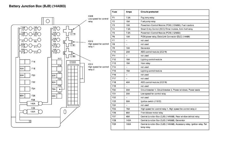
- Engine Compartment Fuse Box: Situated in the engine bay, this box protects critical engine management systems, headlights, fuel pump, and other essential components.
Key specifications to be aware of include the fuse amperage rating, denoted by a number on the fuse itself (e.g., 5A, 10A, 15A, 20A, 30A). Using the correct amperage fuse is crucial to prevent circuit overload and potential fire hazards.
The main parts of the fuse box diagram include:
- Fuse Symbols: Represent the type of circuit protection used (e.g., standard blade fuse, cartridge fuse).
- Amperage Ratings: Indicates the maximum current a fuse can handle before blowing.
- Circuit Descriptions: Explains what components or systems each fuse protects (e.g., "Headlight (Left)," "Power Window (Driver)").
- Relay Locations: Shows the physical position of relays within the fuse box and their corresponding functions (e.g., "Fuel Pump Relay," "Starter Relay").
Understanding Fuse Box Symbols
Fuse box diagrams use a standardized set of symbols to represent different types of fuses, relays, and connections. Deciphering these symbols is key to effectively using the diagram.
- Fuse Symbol: The most common symbol is a simple rectangle with a wavy line through it. This represents a standard blade fuse.
- Relay Symbol: Relays are typically represented by a square or rectangle with internal contacts. The diagram often indicates which terminals are normally open (NO) and normally closed (NC).
- Lines: Solid lines indicate direct electrical connections. Dashed lines may represent connections through wiring harnesses or ground points.
- Color Coding: While not always present on the diagram itself, wiring harnesses often use color-coded wires. Knowing the color code standards for Nissan vehicles can aid in tracing circuits.
The amperage rating is always clearly marked next to the fuse symbol on both the diagram and the fuse itself. Always match the replacement fuse amperage to the original fuse amperage.
How It Works: Circuit Protection
The fuse box works as a central distribution point for electrical power and a protective mechanism against overcurrent. Each fuse is a sacrificial element in the circuit. When the current exceeds the fuse's amperage rating, the thin wire inside the fuse melts (blows), interrupting the circuit and preventing damage to sensitive components. This protects the wiring and the components connected to that circuit from overheating or failing due to excessive current draw.
Relays, on the other hand, act as electrically controlled switches. They allow a low-current circuit (e.g., a dashboard switch) to control a high-current circuit (e.g., headlights or starter motor). This prevents excessive current from flowing through the dashboard switches, which could damage them. When the low-current circuit is energized, it activates the relay, which then closes the high-current circuit.
Real-World Use: Basic Troubleshooting
Here's a basic troubleshooting scenario:
- Symptom: The radio isn't working.
- Step 1: Consult the 2006 Altima fuse box diagram to locate the fuse associated with the radio (e.g., "Radio" or "Audio System").
- Step 2: Physically inspect the fuse in the interior fuse box. Look for a broken filament inside the fuse. A blown fuse will have a visible gap in the metal strip inside.
- Step 3: If the fuse is blown, replace it with a new fuse of the same amperage rating.
- Step 4: Test the radio. If it works, the problem is solved. If the fuse blows again immediately, there's likely a short circuit in the radio wiring or the radio itself. Further investigation is required.
If you suspect a relay issue, you can often test it by swapping it with a known good relay of the same type. For example, if the headlights aren't working, you can swap the headlight relay with the horn relay (if they are the same type) to see if the headlights then function. If they do, the original relay is likely faulty.
Safety Precautions
Working with automotive electrical systems can be dangerous. Observe these safety precautions:
- Disconnect the Battery: Before working on any electrical component, disconnect the negative battery terminal to prevent short circuits and electrical shocks.
- Use Proper Tools: Use insulated tools designed for automotive electrical work.
- Never Exceed Fuse Ratings: Never replace a fuse with a higher amperage fuse. This can overload the circuit and cause a fire. Using a lower amperage fuse might seem okay, but often results in the fuse blowing too easily.
- Identify High-Risk Components: Be extra cautious when working around components like the airbag control module (SRS) and the anti-lock braking system (ABS). These systems can be sensitive to electrical interference and may require specialized handling.
- Avoid Moisture: Keep the fuse box and surrounding area dry to prevent corrosion and short circuits.
The engine compartment fuse box, in particular, contains fuses and relays for critical engine management systems. Tampering with these circuits without proper knowledge can lead to serious engine damage or safety issues.
Always refer to the factory service manual for specific procedures and wiring diagrams related to your 2006 Nissan Altima.
We have a downloadable version of the 2006 Nissan Altima fuse box diagram available. You can download it to have a convenient reference on hand for your projects and repairs.