
2006 Nissan Altima Radio Wiring Diagram
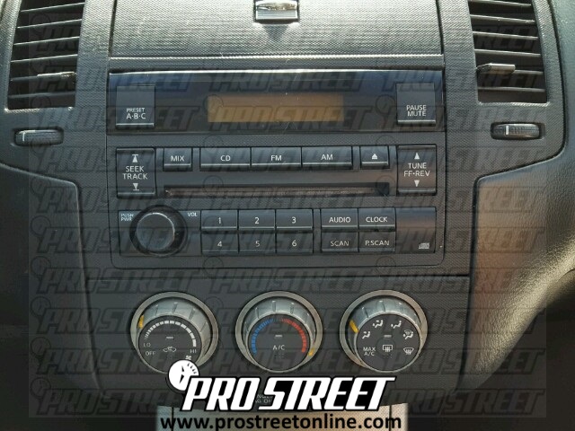
So, you're diving into the audio system of your 2006 Nissan Altima? Smart move! Whether you're upgrading your head unit, fixing a speaker issue, or just trying to understand how everything is connected, a radio wiring diagram is your best friend. This article breaks down the 2006 Altima radio wiring diagram, explaining everything you need to know to tackle your project with confidence. We’re aiming to give you a solid, practical understanding.
Purpose of the 2006 Altima Radio Wiring Diagram
Why bother with a wiring diagram? Well, without it, you're essentially working blind. The diagram serves as a roadmap, outlining every wire connection in your Altima's audio system. This is invaluable for:
- Troubleshooting Audio Problems: Identifying shorts, opens, or incorrect connections causing issues like no sound, static, or blown fuses.
- Head Unit Replacement: Safely and correctly connecting an aftermarket head unit without damaging your car's electrical system.
- Speaker Upgrades: Knowing which wires go to which speakers, preventing incorrect impedance matching which can damage your new speakers or your head unit.
- Adding Amplifiers or Subwoofers: Locating the correct signal and power wires for integration.
- Learning Your Car's Electrical System: Gaining a deeper understanding of how your car's electronics are wired, which can be helpful for future repairs.
Key Specs and Main Parts of the 2006 Altima Radio Wiring Diagram
Let's get down to the nitty-gritty. The 2006 Altima's radio system typically includes the following components:
- Head Unit (Radio): The brain of the operation. It provides the user interface, processes audio signals, and sends power to the speakers. This is also often referred to as the source unit.
- Speakers: The components that convert electrical signals into audible sound. The Altima typically has speakers in the front doors, rear deck, and sometimes tweeters near the A-pillars.
- Antenna: Receives radio signals.
- Amplifier (Optional): Some Altima models, especially those with Bose audio systems, have a separate amplifier to boost the audio signal before it reaches the speakers. This is crucial to know as the wiring is significantly different.
- Wiring Harnesses: Bundles of wires that connect the various components. The two main harnesses connected to the radio are for power/ground/illumination and speaker connections.
When examining the diagram, pay close attention to the following specifications:
- Wire Colors: Each wire is identified by a unique color code. For example, a wire might be labeled "Red/White," indicating a red wire with a white stripe.
- Wire Gauge: The thickness of the wire, typically measured in American Wire Gauge (AWG). This is important for ensuring the wire can handle the current load. Speaker wires are often 16-18 AWG, while power wires might be thicker (12-14 AWG).
- Connector Types: The diagram will show the types of connectors used to connect the various components. Common connector types include Molex and ISO connectors. Identifying these helps when you need to purchase adapters.
- Fuse Ratings: The diagram indicates the fuse protecting the radio circuit. This is critical for safety; always replace a blown fuse with one of the same amperage rating.
- Grounding Points: The diagram shows the locations where the radio and amplifier are grounded to the car's chassis. A good ground connection is essential for proper operation.
Decoding the Symbols and Colors
Understanding the symbols and colors in the wiring diagram is crucial for accurate interpretation.
Lines
- Solid Lines: Represent wires connecting different components.
- Dashed Lines: Often indicate shielded wires or connections to other systems.
- Lines with Arrows: Show the direction of current flow.
Colors
Wire colors are standardized but can vary slightly depending on the specific trim level and year of your Altima. However, some common color codes include:
- Red: Typically indicates a constant 12V power supply (battery).
- Yellow: Usually represents a switched 12V power supply (ignition).
- Black: Always indicates ground.
- Blue: Often used for the remote turn-on lead for an amplifier.
- White, Gray, Green, Purple: Typically speaker wires with a matching color paired with a black stripe for the corresponding negative speaker lead.
- Orange: Often used for illumination.
Always double-check the color codes in your specific diagram against the actual wires in your car to ensure accuracy. Don't rely solely on memory!
Icons
Wiring diagrams use icons to represent components like:
- Resistors: A zig-zag line.
- Capacitors: Two parallel lines.
- Ground: A series of lines decreasing in length.
- Fuse: A wavy line inside a rectangle.
- Speakers: Circle with a cross.
How It Works: Tracing the Circuit
Let's walk through a simplified example of how the radio circuit works. When you turn on the ignition, the yellow wire (switched 12V) receives power. This activates the radio. The radio then draws power from the red wire (constant 12V) to maintain its memory and settings. The radio sends audio signals to the speakers through the speaker wires. If your Altima has a separate amplifier, the radio sends a low-level signal to the amplifier, which then boosts the signal and sends it to the speakers.
Understanding this basic flow allows you to trace the circuit and identify potential problems. For example, if the radio doesn't turn on, you would first check the fuse. If the fuse is good, you would then check the yellow and red wires for power using a multimeter. If there is no power on either wire, you would then trace the wires back to the power source to identify the break in the circuit.
Real-World Use: Basic Troubleshooting Tips
Here are some common problems and how to troubleshoot them using the wiring diagram:
- No Power to the Radio: Check the fuses first! Use a multimeter to verify voltage on the red and yellow wires. Ensure the black wire has a solid ground connection.
- No Sound from Speakers: Verify the speaker connections are secure. Use a multimeter to check the speaker wires for continuity. If you have an amplifier, check its power, ground, and remote turn-on connections.
- Static or Distortion: Check the speaker wires for damage or shorts. Ensure the antenna is properly connected. If the problem only occurs on certain stations, the antenna may be faulty.
- Blown Fuses: Identify the cause of the overload. Common culprits include shorted speaker wires or a faulty head unit. Don't just replace the fuse without finding the source of the problem!
Safety Considerations
Working with car electrical systems can be dangerous. Always disconnect the negative terminal of the battery before working on the wiring. This prevents accidental shorts and potential damage to your car's electrical system. Be especially careful when working around the airbag system. The wiring diagram will show the location of the airbag control module and related wiring. Mishandling these components can cause the airbags to deploy, resulting in serious injury.
Also, be aware that aftermarket accessories, such as high-powered amplifiers, can place a significant load on your car's electrical system. Ensure your wiring is appropriately sized for the load and that you have a properly rated fuse. Consider upgrading the battery and alternator if necessary.
Finally, be extremely cautious when identifying wires by color. While color codes are generally standardized, they can vary. Always use a multimeter to verify the function of a wire before connecting it to another component.
And remember, if you're not comfortable working with electrical systems, it's always best to consult a qualified professional.
We have the complete 2006 Nissan Altima Radio Wiring Diagram file available for you. This detailed diagram will be an invaluable resource as you work on your car's audio system. Download it now and get started!