2006 Nissan Armada Fuse Box Diagram
The 2006 Nissan Armada is a robust vehicle, but like any machine, its electrical system can experience issues. Understanding the fuse box diagram is crucial for troubleshooting electrical problems, performing modifications, or simply learning more about your vehicle's inner workings. This guide provides a detailed breakdown of the 2006 Nissan Armada fuse box, empowering you to diagnose and resolve electrical issues with confidence.
Purpose of the Fuse Box Diagram
The fuse box diagram is your roadmap to the Armada's electrical system. It identifies the location and function of each fuse and relay. This is invaluable for several reasons:
- Troubleshooting Electrical Issues: When an electrical component malfunctions (e.g., headlights, radio, power windows), the fuse box diagram helps you quickly identify the corresponding fuse and determine if it's blown.
- Performing Modifications: If you're adding aftermarket accessories like auxiliary lights or a new stereo, you'll need to tap into the Armada's electrical system. The diagram helps you find suitable fuse locations and understand the circuit's current capacity.
- Understanding Your Vehicle: Even if you're not experiencing problems, studying the fuse box diagram provides a deeper understanding of how your Armada's electrical systems are organized.
- Preventative Maintenance: Knowing the fuse locations can help with preventative maintenance checks, such as ensuring fuses are properly seated and free of corrosion.
Key Specs and Main Parts of the 2006 Nissan Armada Fuse Box
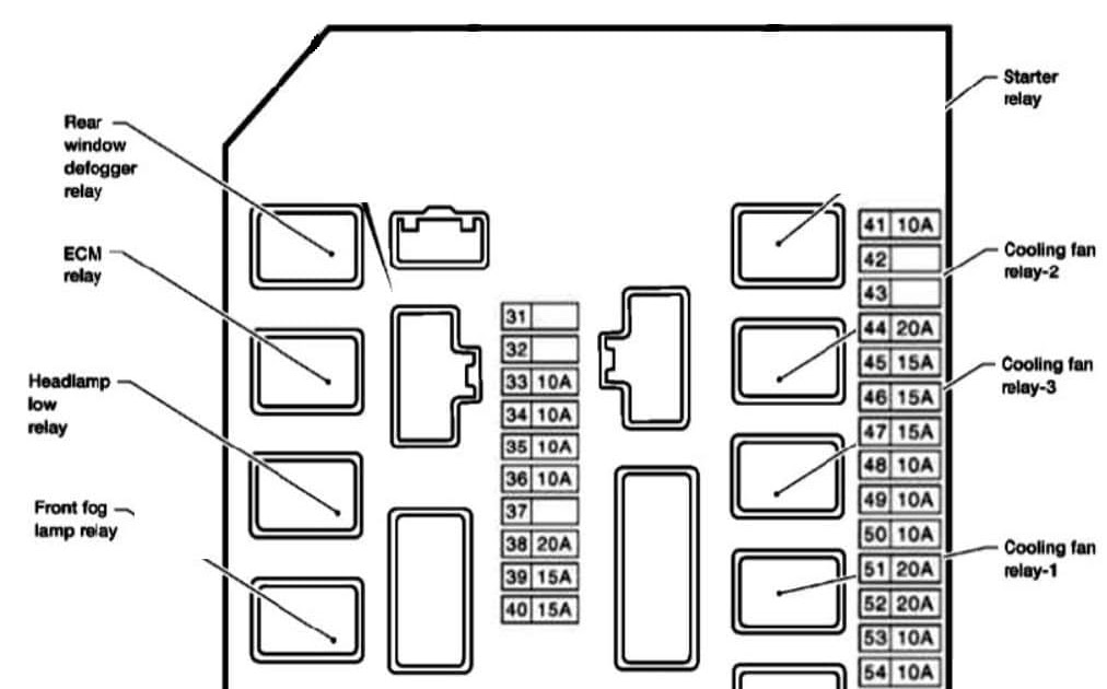
The 2006 Nissan Armada typically has multiple fuse boxes located in different areas of the vehicle. The two primary locations are:
- Interior Fuse Box: Located inside the cabin, usually on the driver's side, often beneath the dashboard or behind a panel. This fuse box primarily protects circuits for interior components like the radio, power windows, interior lights, and climate control.
- Engine Compartment Fuse Box: Located under the hood, typically near the battery. This fuse box protects circuits for critical engine components, headlights, and other exterior systems.
Key Components:
- Fuses: These are safety devices designed to protect electrical circuits from overcurrent. They consist of a thin wire that melts and breaks the circuit if the current exceeds a specific rating. Fuses are rated in amperes (amps), indicating the maximum current they can handle. Common amperage ratings include 5A, 7.5A, 10A, 15A, 20A, 25A, 30A, and 40A.
- Relays: These are electromechanical switches that allow a low-current circuit to control a high-current circuit. They're used to switch on/off components like the headlights, starter motor, and fuel pump. A relay typically consists of a coil, a set of contacts (normally open or normally closed), and a control circuit.
- Fuse Box Housing: The plastic enclosure that houses the fuses and relays. It's designed to protect the electrical components from the elements and provide a secure mounting point.
- Fuse Puller: A small plastic tool used to safely remove fuses from the fuse box without damaging them. It is often clipped to the inside of the fuse box lid.
Understanding Fuse Box Diagram Symbols
The fuse box diagram uses various symbols to represent different electrical components and their functions. Here's a breakdown of common symbols:
- Lines: Lines on the diagram represent electrical wires connecting different components. Thicker lines often indicate higher-current circuits.
- Colors: Wire colors are often indicated on the diagram, which helps to identify the specific wire in the harness. Common wire colors include red, black, blue, yellow, green, and white.
- Fuse Symbol: Usually depicted as a squiggly line enclosed in a rectangle. The amperage rating is often printed next to the symbol.
- Relay Symbol: Typically represented as a coil and a set of contacts.
- Component Icons: Icons are used to represent specific electrical components, such as headlights, wipers, and the horn. These may vary slightly depending on the diagram.
It's crucial to refer to the specific diagram for your 2006 Nissan Armada, as there may be variations based on the trim level and options. The diagram is typically located on the inside of the fuse box cover or in the owner's manual.
How It Works: From Power Source to Component
Understanding how the electrical system works will enhance your ability to troubleshoot issues. Here's a simplified overview:
- Power Source: The battery provides the primary source of electrical power to the Armada.
- Distribution: Power is distributed from the battery to various systems through the wiring harness.
- Fuse Protection: Each circuit is protected by a fuse. If a short circuit or overcurrent occurs, the fuse blows, interrupting the flow of electricity and preventing damage to the wiring and components.
- Relay Control: Relays are used to switch on/off high-current components. A low-current signal from a switch or control module activates the relay, which then closes the contacts and allows power to flow to the component.
- Component Operation: The electrical component (e.g., headlight, motor) receives power and performs its intended function.
Real-World Use: Basic Troubleshooting Tips
Here are some basic troubleshooting tips using the fuse box diagram:
- Identify the Problem: Determine which electrical component is malfunctioning.
- Locate the Fuse: Consult the fuse box diagram to identify the fuse associated with the faulty component.
- Inspect the Fuse: Remove the fuse using a fuse puller and visually inspect it. A blown fuse will have a broken filament inside.
- Replace the Fuse: Replace the blown fuse with a new fuse of the same amperage rating. Never use a fuse with a higher amperage rating, as this could damage the wiring.
- Test the Component: After replacing the fuse, test the component to see if it's working.
- If the Fuse Blows Again: If the new fuse blows immediately or shortly after replacement, there is likely a short circuit or other underlying electrical problem that needs to be investigated by a qualified mechanic.
Example: Your radio is not working. You consult the fuse box diagram and find that fuse #15 in the interior fuse box is labeled "Radio." You remove the fuse and find that it's blown. You replace it with a new fuse of the same amperage (e.g., 10A). The radio now works. Problem solved!
Safety Precautions
Working with the electrical system can be dangerous if proper precautions are not taken. Here are some safety guidelines:
- Disconnect the Battery: Before working on any electrical components, disconnect the negative terminal of the battery to prevent accidental shorts.
- Use Insulated Tools: Use insulated tools to avoid electrical shock.
- Never Bypass Fuses: Never bypass a fuse or use a fuse with a higher amperage rating than specified. This can overload the circuit and cause a fire.
- Identify High-Risk Components: Certain components, such as the airbag system, require specialized knowledge and should only be serviced by a qualified technician. Mishandling these components can result in serious injury.
- Work in a Well-Lit Area: Ensure you have adequate lighting to see what you're doing.
- Refer to the Service Manual: If you're unsure about any procedure, consult the 2006 Nissan Armada service manual.
Accessing the Fuse Box Diagram
The 2006 Nissan Armada fuse box diagram is a valuable resource for any owner or DIY mechanic. Understanding and using it effectively can save you time and money on electrical repairs. It is always advisable to consult the official Nissan service manual for the most accurate and up-to-date information related to your vehicle's specific configuration. We have a digital copy of the diagram available. If you would like to have access, please send a request and we will share the file.