2006 Nissan Maxima Fuse Box Diagram
The 2006 Nissan Maxima, while a robust and well-engineered vehicle, isn't immune to electrical gremlins. And when those gremlins strike, the first line of defense for any experienced DIYer is understanding the fuse box diagram. This article delves deep into the intricacies of the 2006 Maxima's fuse box, empowering you to diagnose, troubleshoot, and repair electrical issues with confidence.
Purpose: Why Understanding the Fuse Box Matters
The fuse box diagram serves as your roadmap to the car's electrical system. It's not just a pretty picture; it's a vital tool for several reasons:
- Troubleshooting Electrical Issues: Identifying a blown fuse is the first step in fixing many electrical problems. The diagram tells you which fuse controls what circuit, saving you hours of guesswork.
- Performing Electrical Modifications: Adding aftermarket accessories like lights, stereos, or alarms requires tapping into existing circuits. The diagram helps you locate suitable power sources and properly fuse your additions.
- Preventing Further Damage: Replacing a blown fuse with one of the correct amperage is crucial. Using the wrong fuse can overload the circuit and cause further damage, potentially leading to a fire.
- General Understanding of Vehicle Systems: Studying the fuse box diagram gives you a broader understanding of how the various electrical components are interconnected.
Key Specs and Main Parts
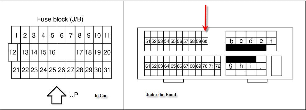
The 2006 Nissan Maxima typically has two main fuse box locations:
- Interior Fuse Box: Located inside the cabin, often under the dashboard on the driver's side. This box primarily houses fuses for interior components like lights, the radio, power windows, and the instrument panel.
- Engine Compartment Fuse Box: Situated in the engine bay, this box protects circuits related to engine management, headlights, cooling fans, and other critical systems.
Both fuse boxes contain the following key components:
- Fuses: These are the sacrificial links in the electrical circuits. They contain a thin wire that melts and breaks the circuit if the current exceeds a safe level. They are rated in Amps, which is a measure of electrical current.
- Relays: Electrically operated switches that control high-current circuits using a low-current signal. They are used to switch on components like headlights, horns, and fuel pumps. Understanding relay locations is crucial for diagnosing issues with these systems.
- Fuse Puller: A small plastic tool included in the fuse box to safely remove and replace fuses. Always use a fuse puller to avoid damaging the fuse or the fuse box.
- Cover/Lid: The protective cover that keeps dirt and moisture out of the fuse box. The fuse diagram is often printed on the inside of this cover.
Symbols: Decoding the Diagram
The fuse box diagram uses various symbols, lines, and colors to represent different components and circuits. Understanding these symbols is essential for correctly interpreting the diagram.
- Lines: Indicate electrical connections between fuses, relays, and components. A solid line usually represents a direct connection, while a dashed line might indicate a switched or controlled connection.
- Colors: May be used to differentiate between circuits or amperage ratings. For example, red might indicate high-amperage fuses, while blue might indicate lower-amperage fuses. However, color-coding is not always consistent, so always refer to the diagram.
- Icons: Represent specific electrical components. Common icons include:
- Headlight: A stylized image of a headlight.
- Horn: A drawing of a horn.
- Cigar Lighter/Power Outlet: A symbol resembling a cigarette lighter or a power outlet.
- Fuel Pump: A symbol representing a fuel pump.
- ECM/ECU: Indicates the Engine Control Module (or Engine Control Unit), the "brain" of the engine.
- Amperage Rating: Each fuse location is labeled with its amperage rating (e.g., 10A, 15A, 20A). This indicates the maximum current that the fuse can safely handle.
How It Works: A System of Protection
The fuse box is essentially a network of safety devices. Each fuse protects a specific circuit from overcurrent. When a fault occurs (e.g., a short circuit), the current in that circuit increases dramatically. This excessive current causes the fuse's thin wire to melt, breaking the circuit and preventing damage to the wiring and connected components. The relay acts as an amplifier/switch. The relay allows a low-current circuit to control a high-current circuit. Consider headlights, for example. The headlight switch is a low-current control, while the headlights themselves require significant current. The relay is used to switch on the high-current headlights when the switch is activated.
Real-World Use: Basic Troubleshooting Tips
Here's how to use the fuse box diagram to troubleshoot common electrical problems:
- Identify the Problem: Determine which electrical component is not working (e.g., the radio, a headlight, or a power window).
- Consult the Diagram: Locate the fuse that corresponds to the non-functioning component using the fuse box diagram.
- Inspect the Fuse: Visually inspect the fuse. A blown fuse will typically have a broken wire inside the glass or a blackened appearance. A multimeter can be used to accurately check continuity, with a blown fuse showing no continuity.
- Replace the Fuse: If the fuse is blown, replace it with a new fuse of the exact same amperage rating. Never use a fuse with a higher amperage rating, as this can overload the circuit and cause a fire.
- Test the Component: After replacing the fuse, test the component to see if it is now working.
- If the Fuse Blows Again: If the new fuse blows immediately or shortly after being replaced, this indicates a more serious problem, such as a short circuit in the wiring or a faulty component. Further diagnosis is required to locate and repair the underlying issue.
Safety: Handle with Care
Working with electrical systems can be dangerous. Always follow these safety precautions:
- Disconnect the Battery: Before working on any electrical components, disconnect the negative terminal of the battery to prevent accidental shorts and electrical shocks.
- Use Proper Tools: Use insulated tools to avoid accidental contact with live wires.
- Never Bypass a Fuse: Bypassing a fuse with a wire or other conductive material is extremely dangerous and can cause a fire.
- Be Aware of Airbags: The airbag system is a sensitive electrical system. If you're working near airbag components, take extra precautions to avoid accidental deployment. Consult the service manual for specific instructions.
- High Current Components: Components like the starter motor solenoid and alternator can have very high current draw. Be extremely careful when working around these components.
Understanding the 2006 Nissan Maxima fuse box diagram is essential for diagnosing and repairing electrical problems. By carefully studying the diagram and following safety precautions, you can confidently tackle many electrical issues and keep your Maxima running smoothly.
We have the full, high-resolution 2006 Nissan Maxima fuse box diagram available for download. This comprehensive diagram will provide you with all the details you need to confidently troubleshoot your vehicle's electrical system.