2006 Nissan Murano Fuse Box Diagram
The 2006 Nissan Murano, like any modern vehicle, relies heavily on a complex electrical system to control everything from the engine management to the interior lights. The fuse box is the central protection point for this system, acting as a circuit breaker to prevent damage from overcurrents. Understanding your Murano's fuse box diagram is absolutely crucial for diagnosing electrical problems, performing aftermarket modifications, or simply maintaining your vehicle. This article will serve as a comprehensive guide to the 2006 Nissan Murano fuse box diagram, enabling you to confidently tackle electrical tasks on your own.
Purpose of the Fuse Box Diagram
Why is a fuse box diagram so important? There are several key reasons:
- Troubleshooting Electrical Issues: When an electrical component stops working, the first place to check is the fuse box. The diagram identifies which fuse corresponds to which circuit, allowing you to quickly locate and test the affected fuse.
- Performing Aftermarket Modifications: Adding accessories like aftermarket lights, sound systems, or alarms requires tapping into the existing electrical system. The diagram helps you identify suitable power sources and choose the appropriate fuse rating for the new circuit, preventing overloads.
- General Maintenance and Knowledge: Understanding the layout of your car's electrical system empowers you to perform basic maintenance tasks and gain a deeper understanding of how your vehicle operates.
- Avoiding Costly Repairs: Identifying and replacing a blown fuse is a simple and inexpensive task. Without the diagram, you could misdiagnose the problem and end up paying a mechanic for a repair you could have easily done yourself.
Key Specs and Main Parts
The 2006 Nissan Murano typically has two main fuse box locations:
- Interior Fuse Box: Located inside the passenger compartment, usually beneath the dashboard on the driver's side. This box typically houses fuses for circuits like the interior lights, radio, power windows, and wipers.
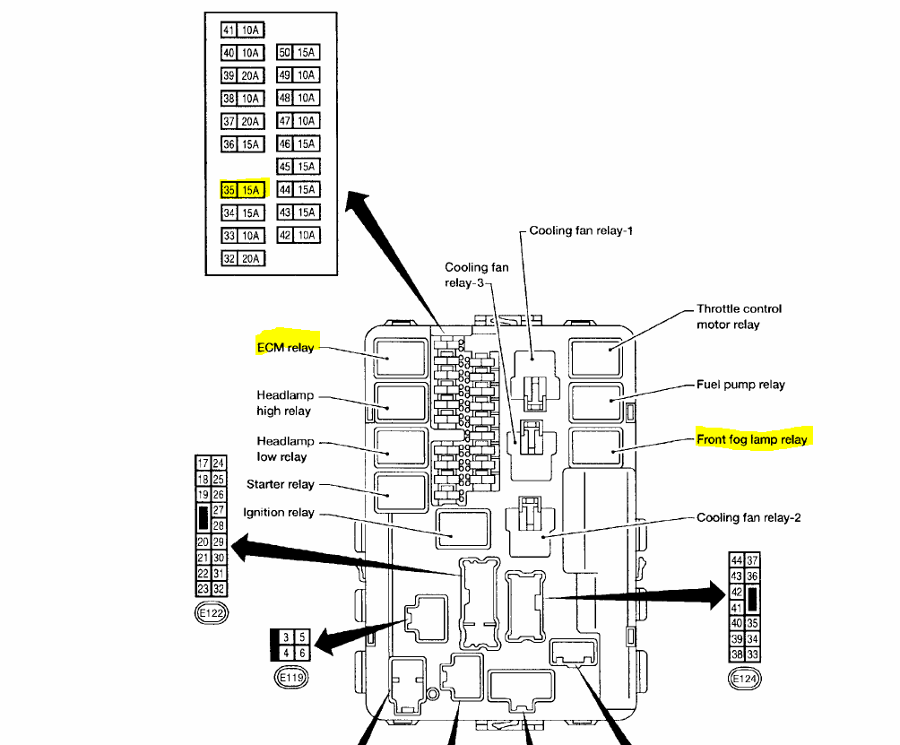
- Engine Compartment Fuse Box: Located under the hood, near the engine. This box typically houses fuses and relays for critical engine components like the fuel pump, ignition system, and cooling fan, as well as larger circuits like the headlights.
The fuse box itself consists of several key components:
- Fuses: These are the protective devices that interrupt the circuit when an overcurrent occurs. They are rated in amperes (amps), which indicates the amount of current they can handle before blowing. Different circuits require different amp ratings.
- Relays: Electromagnetic switches that control high-current circuits using a low-current signal. Relays are commonly used for headlights, starter motors, and other power-hungry components.
- Circuit Breakers: Similar to fuses, but they can be reset after tripping. Circuit breakers are often used for circuits that are prone to temporary overloads, such as power windows.
- The Fuse Box Housing: The physical enclosure that holds the fuses, relays, and circuit breakers.
- The Diagram (Usually a Label): A critical part of the fuse box, usually printed on the inside of the fuse box cover or on a separate label affixed to the box itself. This diagram identifies the function and amperage rating of each fuse, relay, and circuit breaker.
Symbols, Lines, Colors, and Icons Explained
Understanding the symbols used in the fuse box diagram is essential for accurate troubleshooting. While the specific symbols may vary slightly, here are some common ones:
- Lines: Represent electrical circuits. Thicker lines may indicate higher current-carrying capacity.
- Colors: May be used to differentiate between different types of circuits or voltage levels. Unfortunately, color coding is not always standardized and is more commonly found in wiring diagrams than fuse box diagrams.
- Icons: The most crucial part of the diagram. Icons are used to represent the electrical components protected by each fuse. Common icons include:
- Lightbulb: Indicates a lighting circuit (headlights, taillights, interior lights, etc.).
- Fan: Indicates a fan motor circuit (cooling fan, blower motor, etc.).
- Horn: Indicates the horn circuit.
- Radio Speaker: Indicates the audio system circuit.
- Cigarette Lighter: Indicates the accessory power outlet circuit.
- Window: Indicates a power window circuit.
- Wiper: Indicates the windshield wiper circuit.
- Engine: (Often a stylized engine block) Indicates a circuit related to engine management (fuel pump, ignition, etc.).
- Numbers: Indicate the amperage rating of the fuse (e.g., "10A" for a 10-amp fuse).
The diagram typically shows a grid layout that corresponds to the physical arrangement of the fuses in the fuse box. Each square or rectangle in the grid represents a fuse, and the symbol or text next to it identifies its function. Always refer to the diagram specific to your 2006 Nissan Murano, as there can be variations even within the same model year.
How It Works: The Electrical Circuit and Fuses
To understand how the fuse box protects your car's electrical system, it's essential to understand the basics of an electrical circuit. An electrical circuit is a closed loop through which current flows from a power source (e.g., the battery) to a load (e.g., a light bulb) and back to the power source.
The fuse is a sacrificial component in this circuit. It contains a thin wire or strip of metal designed to melt and break the circuit if the current exceeds a predetermined level. This overcurrent can occur due to a short circuit (where a wire accidentally touches ground), an overloaded circuit (where too many devices are drawing power), or a faulty component.
When the fuse blows, it breaks the circuit, preventing excessive current from damaging the wiring and components connected to that circuit. The blown fuse must then be replaced with a new fuse of the same amperage rating.
Real-World Use: Basic Troubleshooting Tips
Here's how to use the fuse box diagram to troubleshoot common electrical problems:
- Identify the Problem: Determine which electrical component is not working (e.g., the radio, the headlights, etc.).
- Locate the Fuse Box Diagram: Refer to your owner's manual or the label inside the fuse box cover.
- Find the Corresponding Fuse: Use the diagram to identify the fuse associated with the non-working component.
- Inspect the Fuse: Visually inspect the fuse. A blown fuse will typically have a broken filament inside the glass or a melted metal strip.
- Test the Fuse (Optional): Use a multimeter to test the fuse for continuity. If the multimeter shows no continuity, the fuse is blown.
- Replace the Fuse: Replace the blown fuse with a new fuse of the same amperage rating. Never use a fuse with a higher amperage rating, as this could damage the wiring and components.
- Test the Component: After replacing the fuse, test the electrical component to see if it is now working.
- If the Fuse Blows Again: If the new fuse blows immediately or shortly after being replaced, there is likely a short circuit or overload in the circuit. Further troubleshooting is required, and you may need to consult a qualified mechanic.
Safety: Highlight Risky Components
Working with automotive electrical systems can be dangerous. Always observe the following safety precautions:
- Disconnect the Battery: Before working on any electrical components, disconnect the negative terminal of the battery to prevent accidental shocks or short circuits.
- Use Insulated Tools: Use tools with insulated handles to protect yourself from electric shock.
- Never Replace a Fuse with a Higher Amperage Rating: This can overload the circuit and cause a fire.
- Avoid Working on the Electrical System in Wet Conditions: Water can conduct electricity and increase the risk of electric shock.
- Be Cautious Around the Airbag System: The airbag system is a sensitive and potentially dangerous electrical system. Avoid tampering with airbag-related circuits unless you are specifically trained to do so. Accidental activation of the airbag can cause serious injury.
- Capacitors in Electronic Control Units (ECUs): Exercise caution when working near ECUs. Some ECUs contain large capacitors that can hold a charge even after the battery is disconnected. Discharging these capacitors requires specialized knowledge and equipment.
Remember, working with the electrical system involves risk. If you are not comfortable performing these tasks yourself, consult a qualified mechanic.
We have a high-resolution, printable PDF of the 2006 Nissan Murano fuse box diagram available for download. This diagram provides a clear and detailed overview of both the interior and engine compartment fuse box layouts. Download it now for easy reference during your troubleshooting and modification projects. This file will give you the clearest most specific information for your vehicle.