2006 Nissan Sentra Relay Box Diagram
Alright, let's dive into the relay box diagram for your 2006 Nissan Sentra. This isn't just some piece of paper; it's the Rosetta Stone to understanding and troubleshooting a significant chunk of your car's electrical system. Whether you're chasing down a phantom power drain, installing aftermarket accessories, or just trying to figure out why your headlights won't turn on, knowing how to read this diagram is invaluable. And guess what? We've got the actual diagram file you can download to follow along.
Purpose: Your Electrical System's Guide
Why bother with a relay box diagram? Simple: modern cars are heavily reliant on electronics. Relays act as electrically controlled switches, allowing low-current circuits to control high-current circuits. The diagram is your roadmap to understanding which relay controls what, where it's located, and how it's connected. It's essential for:
- Troubleshooting Electrical Issues: Identifying a faulty relay or fuse that's causing a specific component to malfunction (e.g., fuel pump, starter motor, air conditioning).
- Installing Aftermarket Accessories: Safely tapping into the electrical system to power new lights, a sound system, or other electronic upgrades. You need to know which circuits can handle the extra load and where to connect without causing damage.
- General Maintenance and Repair: Understanding the relationship between different components and circuits, making it easier to diagnose and fix a wide range of electrical problems.
- Learning About Automotive Electrical Systems: Gaining a deeper understanding of how your car's electrical system works, which can empower you to perform more complex repairs and modifications.
Key Specs and Main Parts of the 2006 Sentra Relay Box
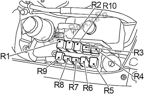
The 2006 Nissan Sentra typically has two main relay boxes: one located in the engine compartment (the IPDM E/R - Intelligent Power Distribution Module Engine Room) and another inside the cabin, often under the dashboard on the driver's side (sometimes referred to as the BCM - Body Control Module, although this encompasses more than just the relay functions). The engine compartment relay box is generally responsible for controlling engine-related components, while the interior relay box handles functions like lighting, wipers, and the HVAC system.
Key Specs to consider:
- Relay Type: Miniature or micro relays are common. The diagram will usually indicate the relay type, often using a code that corresponds to a specific manufacturer's part number.
- Fuse Ratings: Each fuse is designed to protect a specific circuit with a certain amperage rating (e.g., 10A, 15A, 20A). Never replace a fuse with one of a higher amperage rating, as this can overload the circuit and cause a fire.
- Wire Gauge: The thickness of the wires used in the circuits. Thicker wires can handle more current. The diagram may not explicitly state the wire gauge, but it can often be inferred based on the amperage rating of the circuit.
- Voltage: The system operates at 12V DC (Direct Current).
Main Parts as Shown in the Diagram:
- Relays: Electromechanical switches that use a small current to control a larger current. They have a coil, a common contact, a normally open contact, and a normally closed contact (sometimes only NO or NC are present).
- Fuses: Overcurrent protection devices that blow (break the circuit) when the current exceeds a certain level.
- Connectors: Plugs that connect different parts of the wiring harness. These are often numbered or lettered to help identify them.
- Wiring: The conductive pathways that carry electricity.
- Ground Points: Locations where the electrical system is connected to the car's chassis, providing a return path for the current.
Decoding the Symbols: Making Sense of the Lines and Icons
Understanding the symbols is crucial for interpreting the diagram. Here's a breakdown of common symbols you'll encounter:
- Lines: Solid lines represent wires. Dotted lines may indicate shielded wires or connections that are optional or not always present.
- Colors: Wires are often color-coded. The diagram should include a color code legend (e.g., "BL" for blue, "R" for red, "GR" for green, "BK" for black).
- Relay Symbol: A rectangle with a coil inside and a switch symbol next to it. The switch symbol shows the normally open (NO) and normally closed (NC) contacts.
- Fuse Symbol: A zigzag line inside a rectangle.
- Connector Symbol: A circle or a rectangle with lines pointing to the wires connected to it. Connector pins will be numbered.
- Ground Symbol: Looks like a series of stacked triangles, indicating a connection to the vehicle's chassis ground.
- Component Symbols: Various symbols are used to represent different components, such as headlights, motors, sensors, and control modules. The diagram should have a key that identifies these symbols.
Example: A solid red line (R) connecting a fuse to a relay's coil means that the fuse protects the power supply to the relay's coil. A black line (BK) connected to a ground symbol indicates a ground connection.
How It Works: From Power Source to Component Activation
The 2006 Sentra's electrical system operates on a 12-volt direct current (DC) system. Power flows from the battery through various circuits, controlled by switches, relays, and fuses. When you turn the ignition key, for instance, it activates a series of relays that power up the engine control unit (ECU), fuel pump, and other critical components.
Simplified Relay Operation:
- Control Circuit: A small current flows through the relay's coil when a switch is activated (e.g., when you turn on your headlights).
- Magnetic Field: The current flowing through the coil creates a magnetic field.
- Armature Activation: The magnetic field pulls an armature (a moving part) inside the relay.
- Contact Closure: The armature movement causes the contacts to close, completing the high-current circuit.
- Component Activation: The closed circuit allows current to flow to the component being controlled (e.g., the headlights), turning it on.
The relay allows a low-current circuit (the control circuit) to switch a high-current circuit (the load circuit) without requiring a high-current switch. This is important because high-current switches can be large, expensive, and prone to arcing.
Real-World Use: Basic Troubleshooting Tips
Here's how you can use the relay box diagram to troubleshoot common electrical problems:
- Component Not Working: If a component isn't working, start by checking the fuse associated with that component in the diagram. If the fuse is blown, replace it with a fuse of the same amperage rating. If the fuse blows again immediately, there's likely a short circuit in the wiring or the component itself.
- Relay Issues: If the fuse is good, check the relay. You can often swap the relay with a known good relay of the same type (e.g., from a less critical circuit like the rear window defogger) to see if that fixes the problem. You can also test the relay using a multimeter to check for continuity and voltage.
- Wiring Problems: Use the diagram to trace the wiring from the power source to the component. Look for damaged wires, loose connections, or corrosion. A multimeter can be used to check for continuity and voltage along the circuit.
- Power Drain: If your battery keeps dying, there might be a parasitic draw (a component that's drawing power even when the car is off). Use the diagram to systematically disconnect circuits one by one to identify the source of the draw.
Example: If your headlights aren't working, check the headlight fuse and relay using the diagram. If both are good, use the diagram to trace the wiring from the relay to the headlights, looking for breaks or shorts in the circuit.
Safety: Handle with Care!
Working with electrical systems can be dangerous. Always take these precautions:
- Disconnect the Battery: Before working on any electrical components, disconnect the negative (-) terminal of the battery to prevent accidental shocks or short circuits.
- Use Proper Tools: Use insulated tools designed for electrical work.
- Work in a Well-Lit Area: Ensure you have adequate lighting to see what you're doing.
- Don't Work with Wet Hands: Water is a conductor of electricity.
- Never Bypass Fuses: Fuses are there to protect the circuit. Bypassing them can lead to overheating and fires.
- Pay Attention to High-Current Circuits: The starter motor and alternator circuits carry very high currents and can deliver a powerful shock. Be extra careful when working with these circuits.
Risk Alert: The airbag system also utilizes relays and wiring within the electrical system. Tampering with the airbag system can be extremely dangerous and could result in accidental airbag deployment, causing serious injury. If you suspect a problem with the airbag system, it's best to consult a qualified technician.
Remember, safety is paramount. If you're not comfortable working on electrical systems, it's always best to consult a qualified mechanic.
Now that you have a solid understanding of the 2006 Nissan Sentra relay box diagram, you're well-equipped to tackle a wide range of electrical troubleshooting and repair tasks. Remember to always double-check your work and prioritize safety. Good luck!
As mentioned earlier, we have the full 2006 Nissan Sentra relay box diagram available for download. This will give you a visual aid as you work through the system and refer back to this article.