2006 Nissan Titan Fuse Box Diagram
For the intermediate car owner, modder, or DIY mechanic tackling electrical issues on a 2006 Nissan Titan, understanding the fuse box diagram is absolutely crucial. It’s more than just a map; it's your guide to safely diagnosing and resolving a range of electrical problems, preventing potential damage, and even customizing your truck. This article provides an in-depth look at the 2006 Nissan Titan fuse box diagram, breaking down its key components, symbols, and real-world applications. Consider this your definitive resource.
Purpose and Importance
Why bother with a fuse box diagram? Several reasons. First and foremost, it's invaluable for electrical repairs. When an electrical component fails – a headlight, the radio, a power window – the first step is often checking the corresponding fuse. The diagram tells you exactly which fuse to inspect. Second, it's essential for understanding your vehicle's electrical system. Knowing which circuits power which components gives you a deeper understanding of how your Titan works. Third, for those interested in modifications, the diagram is indispensable. Adding aftermarket accessories, like lights or a stereo system, requires tapping into existing circuits, and the diagram ensures you do so safely and correctly, avoiding overloads and potential fires. Finally, having access to this information saves you money on costly diagnostic fees from professional mechanics. Armed with the diagram and a multimeter, you can pinpoint many electrical issues yourself.
Key Specs and Main Parts
The 2006 Nissan Titan typically has two main fuse boxes: one located in the engine compartment, and another located inside the cabin, often under the dashboard on the driver's side. Some models might have a third, smaller fuse box near the battery or under the rear seat. Each fuse box houses a collection of fuses and relays, each protecting a specific electrical circuit.
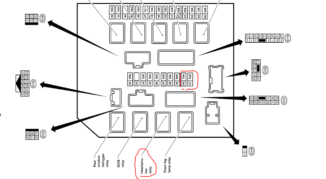
Engine Compartment Fuse Box
This box typically houses fuses and relays related to engine management, headlights, air conditioning, the horn, and other critical vehicle systems. The fuses here are generally larger amperage ratings than those inside the cabin, reflecting the higher current demands of these systems.
Interior Fuse Box
The interior fuse box usually contains fuses for interior lighting, the radio, power windows, power door locks, the instrument cluster, and other comfort and convenience features. These circuits typically draw less current.
The fuse box diagram itself is usually found on the inside of the fuse box cover. This diagram is a visual representation of the fuse and relay layout, indicating the function and amperage rating of each component.
Symbols and Diagram Interpretation
Understanding the symbols on the fuse box diagram is crucial for correct interpretation. Here's a breakdown of common symbols:
- Lines: Lines on the diagram represent electrical circuits. A solid line generally indicates a direct connection, while a dashed line may indicate a connection through a switch or relay.
- Colors: Color coding is not always consistent, but often, different colors indicate different voltage levels or circuit types. However, rely more on the legend provided with the diagram than on assuming a specific color convention.
- Fuse Symbol: Fuses are typically represented by a simple line interrupted in the middle, often with a small rectangle or square around it.
- Relay Symbol: Relays are usually depicted as a square or rectangle with a coil symbol inside, along with connection points. A relay is an electrically operated switch, using a small current to control a larger current circuit.
- Amperage Rating: Each fuse will have a number next to it, indicating its amperage rating (e.g., 10A, 15A, 20A). This is the maximum current that the fuse can handle before it blows.
- Component Icons: The diagram often uses icons to represent the component protected by each fuse. These icons can vary, but common ones include headlights, radios, windows, and various engine components. Consult the diagram legend for clarification.
Important Note: Always refer to the specific fuse box diagram for your 2006 Nissan Titan. While general layouts are similar, there can be variations based on trim level and optional equipment.
How It Works
The fuse box is the central distribution point for electrical power in your Titan. Power flows from the battery through the ignition switch and then to the fuse boxes. Each fuse protects a specific circuit. When excessive current flows through a circuit – due to a short circuit, overload, or component failure – the fuse's internal element melts, breaking the circuit and preventing damage to the wiring and components. The relay functions as an electrically operated switch. The ECU, switches or sensors can activate the relay, enabling or disabling a specific circuit. This allows low-current signals to control high-current devices, like starter motors or fuel pumps.
Real-World Use and Basic Troubleshooting
Here’s how to use the fuse box diagram for troubleshooting:
- Identify the Problem: Determine which component is malfunctioning (e.g., headlight not working, radio dead).
- Locate the Relevant Fuse: Consult the fuse box diagram to identify the fuse associated with that component.
- Inspect the Fuse: Visually inspect the fuse. A blown fuse will have a broken filament. You can also use a multimeter set to continuity to test the fuse. A good fuse will show continuity (a beep or a reading close to zero ohms).
- Replace the Fuse: If the fuse is blown, replace it with a fuse of the same amperage rating. Using a higher amperage fuse can damage the wiring and components.
- Test the Component: After replacing the fuse, test the component to see if it now works.
- If the Fuse Blows Again: If the new fuse blows immediately, there's likely a short circuit in the wiring or the component itself. Further investigation is needed, potentially involving tracing the wiring and testing the component.
Example: Your radio isn't working. You check the interior fuse box diagram and find a fuse labeled "Radio" with a 15A rating. You visually inspect the fuse and see that the filament is broken. You replace the fuse with a new 15A fuse, and the radio now works.
Safety Precautions
Working with electrical systems can be dangerous. Here are some important safety precautions:
- Disconnect the Battery: Before working on any electrical system, disconnect the negative terminal of the battery to prevent accidental shorts or shocks.
- Use the Correct Tools: Use insulated tools designed for automotive electrical work.
- Never Bypass a Fuse: Never bypass a fuse by using a wire or other conductive material. This can cause a fire.
- Be Aware of High-Current Components: Be especially cautious around high-current components like the starter motor, alternator, and battery. These components can deliver a significant electrical shock.
- Work in a Well-Lit Area: Ensure you have adequate lighting to see what you're doing clearly.
Warning: The airbag system uses high-current circuits. Consult the service manual before working near airbag components. Mishandling airbags can result in serious injury.
Diagram Availability
We understand the importance of having the actual diagram for your convenience. We have a digital file of the 2006 Nissan Titan fuse box diagram available for download. This will provide you with a clear and readily accessible reference when working on your vehicle's electrical system.