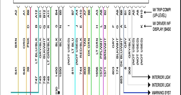
2006 Pontiac Grand Prix Radio Wiring Diagram
Let's dive into the wiring of the 2006 Pontiac Grand Prix radio system. Understanding this wiring diagram is crucial if you're tackling audio upgrades, troubleshooting electrical issues, or simply want a deeper understanding of your car's electronics. This guide provides a detailed breakdown of the diagram, key components, and practical troubleshooting tips.
Purpose of the Radio Wiring Diagram
A radio wiring diagram is essentially a roadmap of the electrical connections within your car's audio system. It shows how the radio (also known as the head unit), speakers, antenna, and other components are interconnected. This information is vital for:
- Repairing a faulty radio: Pinpointing shorts, opens, or incorrect wiring.
- Upgrading your audio system: Adding aftermarket amplifiers, speakers, or subwoofers while understanding the existing wiring configuration.
- Installing a new head unit: Connecting the new head unit to the car's existing wiring harness.
- Diagnosing electrical problems: Isolating audio-related electrical issues from other car systems.
- General automotive learning: Understanding how different car systems interact.
Key Specs and Main Parts
Before dissecting the diagram itself, let's identify the major parts involved. The 2006 Grand Prix, depending on the trim level, came with a few different audio configurations. We'll focus on the common single-DIN or double-DIN factory radio, which is the most prevalent.
- Head Unit (Radio): The brains of the system. It receives radio signals, plays CDs, and controls the audio output.
- Speakers: Converts electrical signals from the head unit or amplifier into sound. Typically, there are four speakers: front left, front right, rear left, and rear right. Some models might have tweeters in the front doors or A-pillars, and potentially a subwoofer.
- Antenna: Receives radio signals.
- Wiring Harness: A collection of wires bundled together that connect the head unit to the car's electrical system and speakers. This is the key interface point for most modifications.
- Power Source: The car's battery and associated fuses supply power to the radio. There are typically two power wires: a constant 12V+ (for memory retention) and a switched 12V+ (that turns the radio on and off with the ignition).
- Ground: Provides a return path for the electrical current. A good ground connection is crucial for proper operation.
- Remote Turn-On Wire (Optional): If an amplifier is present, a remote turn-on wire from the head unit signals the amplifier to turn on when the radio is powered up.
- Chassis Ground: The physical metal frame of the car, used as the ultimate ground point for the car's electrical system.
Understanding the Wiring Diagram Symbols
Wiring diagrams use a standardized set of symbols and conventions to represent electrical components and connections. Let's decipher some common symbols found in the 2006 Grand Prix radio wiring diagram:
- Solid Lines: Represent wires. Thicker lines often indicate wires carrying higher current.
- Dotted Lines: May represent shielded cables or wiring that is part of a specific module.
- Circles: Can represent connectors or terminals.
- Squares: Often represent components or modules.
- Color Codes: Wires are typically identified by their color (e.g., RED, BLK, YEL, GRN, BLU). Knowing these color codes is critical for identifying the correct wires. The diagram legend will explain these codes.
- Ground Symbol: Usually a series of descending horizontal lines, indicating a connection to the car's chassis ground.
- Fuse Symbol: A squiggly line inside a rectangle, indicating a fuse.
- Speaker Symbol: A circle with a cross in the middle.
- Connector Numbers: Connectors are often numbered (e.g., X1, X2) to help you locate them in the car.
The diagram will also use acronyms. Pay close attention to the legend on the diagram. Terms like BATT (Battery), GND (Ground), ACC (Accessory), and REM (Remote) are frequently used.
How the Radio System Works
Here’s a simplified explanation of how the radio system functions:
- Power Supply: The radio receives power from the car's battery through the constant 12V+ wire and the switched 12V+ wire. The constant wire keeps the radio's memory (presets, settings) alive when the ignition is off. The switched wire activates the radio when the ignition is turned on.
- Signal Reception: The antenna receives radio signals and sends them to the head unit.
- Signal Processing: The head unit tunes to a specific radio frequency or plays audio from a CD.
- Amplification: The head unit amplifies the audio signal. Some models have a built-in amplifier, while others may use an external amplifier.
- Speaker Output: The amplified audio signal is sent to the speakers through the speaker wires. Each speaker has a positive (+) and negative (-) wire. Proper polarity is crucial for sound quality. Reversing the polarity on a speaker can cause phase cancellation and reduce bass response.
- Grounding: All electrical components need a solid ground connection to complete the circuit.
Real-World Use and Basic Troubleshooting
Let's consider a few practical scenarios:
- Radio Not Turning On: Check the fuses related to the radio. Use a multimeter to test for power at the constant and switched 12V+ wires at the radio harness. Verify the ground connection is secure.
- No Sound From One Speaker: Check the speaker wiring connections. Use a multimeter to check the speaker wire continuity. The speaker itself may be damaged. Swap the speaker with another known-good speaker to test.
- Poor Radio Reception: Check the antenna connection to the radio. Inspect the antenna cable for damage.
- Installing an Aftermarket Head Unit: Use a wiring harness adapter specifically designed for the 2006 Grand Prix. This will allow you to connect the new head unit to the car's existing wiring without cutting any wires. Carefully match the wires from the adapter to the wires from the new head unit, using the wiring diagrams for both devices.
When troubleshooting, always disconnect the negative battery terminal to prevent accidental shorts and electrical damage.
Safety Precautions
Working with automotive electrical systems involves inherent risks. Take these precautions:
- Disconnect the Battery: Always disconnect the negative battery terminal before working on any electrical components. This prevents accidental shorts and potential damage.
- Work in a Well-Lit Area: Ensure adequate lighting to clearly see the wiring and components.
- Use Proper Tools: Use insulated tools designed for automotive electrical work.
- Avoid Water: Never work on electrical systems in wet conditions.
- Be Cautious Around Airbags: Airbag systems contain sensitive electronics and can be dangerous if mishandled. Avoid working near airbag components unless you have the proper training.
- Understand Wire Gauges: Do not replace a wire with one of a smaller gauge. Smaller gauge wires can overheat and cause a fire if they're carrying more current than they're designed to handle.
- Fuses Are Important: Never bypass a fuse. Fuses are designed to protect the electrical system from overloads. Replacing a blown fuse with one of a higher amperage can be dangerous.
The airbag system is particularly sensitive. Do not tamper with any wiring or components related to the airbags unless you are a qualified technician. Incorrectly handling airbag systems can result in serious injury.
Remember to consult the official 2006 Pontiac Grand Prix service manual for the most accurate and detailed wiring diagrams and specifications. While this article provides a comprehensive overview, it should not be considered a substitute for professional advice.
We have the 2006 Pontiac Grand Prix Radio Wiring Diagram file available for download. This file provides a detailed visual guide to the radio wiring, helping you with any troubleshooting or modification tasks.