
2006 Silverado Tail Light Wiring Diagram
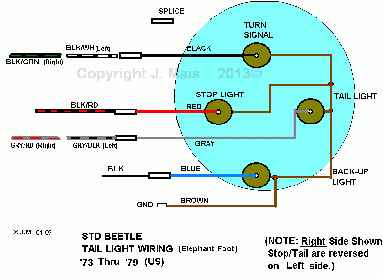
So, you're looking to dive into the tail light wiring of your 2006 Silverado? Good on you! Whether you're troubleshooting a pesky short circuit, planning a cool lighting upgrade, or just want to understand the electrical system better, knowing your way around the tail light wiring diagram is essential. This article will break down the specifics, equipping you with the knowledge you need to tackle most common tail light issues on your Silverado. And don't worry, we've got the actual diagram ready for you to download at the end – it'll be invaluable.
Purpose of Understanding the Tail Light Wiring Diagram
Let's be clear: the tail light wiring diagram isn't just a pretty picture. It's the roadmap to your Silverado's rear lighting system. It allows you to:
- Diagnose and Repair Faults: Pinpoint wiring issues causing lights to fail, flicker, or behave erratically.
- Install Aftermarket Accessories: Safely and correctly connect new lights, such as LED upgrades, auxiliary lights, or trailer wiring.
- Understand the System: Gain a comprehensive understanding of how the tail lights, brake lights, turn signals, and reverse lights function together.
- Avoid Costly Repairs: By identifying and addressing issues early, you can prevent more significant (and expensive) electrical problems down the road.
Key Specs and Main Parts of the 2006 Silverado Tail Light System
The 2006 Silverado tail light system is relatively straightforward, but understanding its components is critical. The key parts include:
- Tail Light Assemblies: The physical housings containing the bulbs (or LEDs in aftermarket versions) for the various lighting functions.
- Bulbs: Typically incandescent bulbs, although many owners upgrade to LED bulbs for improved brightness and longevity. Original incandescent bulbs will likely be 3057 or 3157 type bulbs for the brake/tail lights and turn signals, and a smaller bulb, usually a 194, for the side marker or license plate illumination.
- Sockets: The receptacles that hold the bulbs and provide electrical connections.
- Wiring Harness: A bundle of wires that connect the various components of the system, running from the front of the vehicle to the tail light assemblies.
- Connectors: Plugs that connect the wiring harness to the tail light assemblies and other components.
- Grounding Points: Locations where the wiring harness is connected to the vehicle's chassis, providing a return path for the electrical current. Proper grounding is crucial for a functioning electrical system.
- Fuses and Relays: Protective devices that prevent damage to the electrical system in case of a short circuit or overload. The relevant fuses are typically located in the under-hood electrical center. Consult your owner's manual for specific fuse locations.
- Body Control Module (BCM): A computer module that controls various functions of the vehicle, including the tail lights. The BCM receives signals from the brake pedal switch, turn signal switch, and other sensors, and then activates the appropriate lights.
Decoding the Wiring Diagram: Symbols, Lines, and Colors
The wiring diagram is a symbolic representation of the electrical system. Understanding these symbols is crucial for interpreting the diagram correctly. Here's a breakdown of the common symbols:
- Lines: Represent wires. The thickness of the line doesn't usually indicate wire gauge in these diagrams but rather emphasizes a specific wire.
- Colors: Each wire is identified by a specific color, such as Red (RD), Black (BK), Brown (BR), Yellow (YE), Green (GR), Blue (BL), etc. These color codes are essential for identifying the correct wires in the harness. Look for color abbreviations near the lines.
- Circles: Represent various components, such as bulbs, sockets, and switches. The specific symbol inside the circle will indicate the type of component.
- Rectangles: Often represent connectors or modules, such as the BCM.
- Ground Symbol: A symbol resembling an inverted triangle or a series of horizontal lines, indicating a connection to the vehicle's chassis ground.
- Splices: Represented by dots where wires connect.
Understanding wire colors is critical. A typical 2006 Silverado diagram may use the following color coding (but always verify with the diagram itself):
- Brown (BR): Tail lights
- Dark Green (DG): Right turn signal and brake light
- Light Green (LG): Left turn signal and brake light
- White (WH): Ground
- Light Blue (LB): Reverse lights
How the Silverado Tail Light System Works
The tail light system works by sending electrical signals from various switches and sensors to the BCM, which then activates the appropriate lights. Here's a simplified explanation:
- Tail Lights: When the headlights are turned on, a signal is sent to the BCM, which then activates the tail lights through the brown wire.
- Brake Lights: When the brake pedal is pressed, a switch sends a signal to the BCM, which then activates the brake lights (using the dark green and light green wires, combined with the turn signal function).
- Turn Signals: When the turn signal lever is activated, a switch sends a signal to the BCM, which then pulses the appropriate turn signal light (also using the dark green and light green wires).
- Reverse Lights: When the vehicle is shifted into reverse, a switch on the transmission sends a signal to the BCM, which then activates the reverse lights (using the light blue wire).
Real-World Use: Basic Troubleshooting Tips
Armed with the wiring diagram, you can troubleshoot common tail light issues. Here are a few tips:
- No Lights at All: Check the fuses first. A blown fuse is the most common cause of a complete tail light failure. Refer to your owner’s manual or the fuse box diagram itself.
- One Light Not Working: Check the bulb first. If the bulb is good, use a multimeter to check for voltage at the socket. If there's no voltage, trace the wiring back to the connector or fuse box. Also, check the ground connection. A corroded or loose ground can cause intermittent or complete failure.
- Flickering Lights: This is often caused by a loose connection or a corroded ground. Inspect the wiring harness and connectors for damage or corrosion. Clean the ground connections with a wire brush.
- Turn Signal Issues: If one turn signal flashes rapidly, it usually indicates a burned-out bulb on that side. However, it can also be caused by a wiring problem.
When testing for voltage, be sure to use a digital multimeter (DMM). Set it to DC voltage and connect the black lead to a known good ground. Probe the connector terminals with the red lead to check for the presence of voltage.
Safety Considerations
Working with electrical systems can be dangerous. Here are some safety precautions:
- Disconnect the Battery: Always disconnect the negative battery cable before working on the electrical system. This will prevent accidental shorts and shocks.
- Use Proper Tools: Use insulated tools designed for electrical work.
- Avoid Working in Wet Conditions: Water and electricity don't mix.
- Be Careful with Wiring: Avoid pulling or stretching wires, as this can damage them.
- Fuses: *Never* replace a fuse with a higher amperage fuse. This can overload the circuit and cause a fire. Use the correct amperage fuse specified in your owner's manual.
Important Note: The BCM is a sensitive electronic component. Avoid exposing it to static electricity. Ground yourself before touching the BCM.
The tail light system involves the high-current brake light circuits. A short circuit in this area can create a fire hazard. Always carefully inspect and repair any damaged wiring. If you're not comfortable working with electrical systems, consult a qualified technician.
We've covered the fundamentals. Now, to truly conquer your 2006 Silverado's tail lights, you'll need the actual wiring diagram. We have the file available for you. You can download it using the link below. Having the diagram in hand while you're troubleshooting or upgrading your lights will make the whole process much smoother and safer. Good luck!