
2006 Toyota Avalon Ignition Coil Diagram
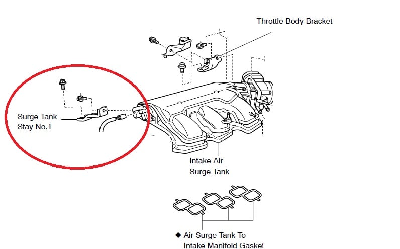
Let's dive into the ignition system of a 2006 Toyota Avalon, specifically focusing on the ignition coil diagram. Understanding this diagram is invaluable, whether you're tackling a misfire, replacing a faulty coil, or simply expanding your automotive knowledge. It’s the roadmap to the spark that ignites the air/fuel mixture in your engine, the heart of its combustion process.
Purpose of the 2006 Toyota Avalon Ignition Coil Diagram
The ignition coil diagram serves several critical purposes. Firstly, it's your guide for diagnosing ignition-related problems. A misfire, rough idling, or a no-start condition often stems from a faulty ignition coil or wiring issue. With the diagram, you can systematically trace the circuit and pinpoint the culprit. Secondly, it's indispensable when replacing ignition coils or other components within the ignition system. Correct wiring is paramount; a mistake can lead to further damage or a non-operational vehicle. Lastly, studying the diagram enhances your overall understanding of automotive electrical systems. It provides a tangible example of how circuits work and how various components interact.
Key Specs and Main Parts
The 2006 Toyota Avalon, depending on the trim level, generally features a 3.5L 2GR-FE V6 engine. This engine uses a coil-on-plug (COP) ignition system. Let's break down the key components:
- Ignition Coils: One coil sits directly on top of each spark plug, eliminating the need for spark plug wires (in most applications). These coils are responsible for stepping up the battery's voltage (typically 12V) to a much higher voltage (around 20,000 - 30,000 volts) needed to create a spark across the spark plug gap.
- Engine Control Module (ECM): This is the brain of the engine. It determines the optimal ignition timing and sends signals to the ignition coils to fire at the correct moment. The ECM relies on various sensors, such as the crankshaft position sensor (CKP) and camshaft position sensor (CMP), to make these calculations.
- Crankshaft Position Sensor (CKP): This sensor monitors the position and speed of the crankshaft. The ECM uses this information to determine when to fire the ignition coils in relation to the piston's position.
- Camshaft Position Sensor (CMP): Similar to the CKP, the CMP monitors the position of the camshaft. This is essential for determining which cylinder is on its compression stroke and needs to be ignited.
- Wiring Harness: The wiring harness provides the electrical connections between all the components of the ignition system. It's crucial that these wires are in good condition and properly connected.
- Spark Plugs: These components are located at the end of the high-voltage circuits and are responsible for creating the spark that ignites the air/fuel mixture.
- Ignition Switch: This sends power to the ignition system.
Key specifications relating to the ignition coils themselves include their primary resistance (resistance of the primary winding) and secondary resistance (resistance of the secondary winding). These values are typically listed in the vehicle's repair manual. Checking these resistances with a multimeter is a common troubleshooting step.
Understanding Symbols on the Diagram
Electrical diagrams use standardized symbols to represent components and connections. Here are some common symbols you'll encounter in a 2006 Toyota Avalon ignition coil diagram:
- Solid Lines: Represent wires. The thickness of the line may indicate the wire gauge (thicker lines usually indicate larger gauge wires capable of carrying more current).
- Dashed Lines: Often represent shielding or ground connections.
- Coil Symbol: A series of loops represents an inductor or coil (in this case, the ignition coil itself).
- Rectangle with Pin Numbers: Represents a connector, often labeled with pin numbers to identify each wire's connection point.
- Ground Symbol: Usually three horizontal lines decreasing in size, indicating a connection to the vehicle's chassis ground.
- ECM Symbol: A box (usually representing the ECM) labeled with I/O (input/output).
Color Coding: Wire colors are crucial for identifying the correct wires in the harness. The diagram will typically include a key indicating the color code (e.g., BLK = Black, RED = Red, BLU = Blue, etc.). Pay close attention to these color codes; incorrect connections can damage the ECM or other components.
How It Works
The ignition system's operation is fairly straightforward, although the internal processes are complex:
- When you turn the ignition key, the ECM receives power.
- The CKP and CMP sensors provide the ECM with information about the crankshaft and camshaft positions.
- Based on this information, along with other sensor inputs (e.g., engine temperature, throttle position), the ECM calculates the optimal ignition timing for each cylinder.
- The ECM sends a low-voltage signal to the primary winding of the appropriate ignition coil.
- This signal energizes the primary winding, creating a magnetic field.
- When the ECM cuts off the current to the primary winding, the magnetic field collapses rapidly.
- This rapid collapse induces a high-voltage surge in the secondary winding of the ignition coil.
- This high-voltage surge travels to the spark plug, creating a spark across the spark plug gap.
- The spark ignites the air/fuel mixture in the cylinder, initiating combustion.
Real-World Use: Basic Troubleshooting Tips
Here are some common troubleshooting scenarios where the ignition coil diagram proves invaluable:
- Misfire Diagnosis: If you're experiencing a misfire (indicated by a rough-running engine and a diagnostic trouble code (DTC) like P0300-P0306), the diagram can help you isolate the faulty coil. Start by swapping coils between cylinders. If the misfire follows the coil, you've likely found the problem. Then use a multimeter to check the primary and secondary coil resistances to make sure the coil is within the correct range for the 2GR-FE engine.
- Wiring Issues: Check the wiring harness for any signs of damage, such as frayed wires, corroded connectors, or loose connections. Use the diagram to verify the wiring connections and ensure that each wire is properly connected to the correct pin on the coil connector and ECM.
- No-Start Condition: If the engine won't start, check for power at the ignition coils using a test light or multimeter. The diagram will show you which wire should have power with the ignition on. If there's no power, trace the circuit back to the ignition switch or ECM.
Using a Multimeter: Familiarize yourself with using a multimeter to check for voltage, continuity, and resistance. The diagram will provide you with the test points and expected values.
Safety Considerations
The ignition system involves high voltages. Always disconnect the negative battery cable before working on the ignition system to avoid electrical shock. Wait a few minutes after disconnecting the battery to allow any residual voltage to dissipate. Never touch the ignition coils or spark plug wires while the engine is running; this can result in a potentially fatal shock.
Be extra careful when working around the ECM. Static electricity can damage sensitive electronic components inside the ECM. Ground yourself properly by touching a metal part of the vehicle before handling the ECM or any of its connectors.
When testing the ignition coils, use a properly rated spark tester to prevent damage to the coils or the ECM. Never ground the spark plug wire directly to the engine block; this can overload the ignition coil and cause it to fail.
If you are not comfortable working with electrical systems, it's best to consult a qualified mechanic. The ignition system is a critical component of the engine, and improper repairs can lead to further damage or a non-operational vehicle.
Disclaimer: Always consult the official Toyota service manual for your specific vehicle model and year. The information provided here is for educational purposes only and should not be considered a substitute for professional advice.
We have the 2006 Toyota Avalon Ignition Coil Diagram file available for download. This diagram is a valuable resource for troubleshooting and repairing your Avalon's ignition system.