2007 Chevrolet Silverado Radio Wiring Diagram
If you're diving into the electrical heart of a 2007 Chevrolet Silverado – whether for a radio upgrade, speaker repair, or just to understand how things tick – a reliable wiring diagram is your best friend. This article will break down the 2007 Silverado radio wiring diagram, explaining its purpose, key components, and how to interpret it, all while keeping safety paramount.
Why This Diagram Matters
The 2007 Silverado radio wiring diagram is much more than just a collection of lines and symbols. It's a roadmap to your truck's audio system. Its primary purposes include:
- Troubleshooting: Identifying faulty wiring, shorts, or open circuits that can cause radio malfunction, speaker issues, or even drain your battery.
- Upgrades and Modifications: Safely installing aftermarket radios, amplifiers, speakers, or subwoofers without damaging the factory wiring.
- Repairing Damaged Wiring: Accurately splicing and reconnecting wires that have been cut, frayed, or damaged by corrosion or accidents.
- Understanding System Function: Gaining a deeper understanding of how the radio and related components are integrated into the vehicle's electrical system.
- Custom Installs: Adding carplay and/or android auto modules.
Key Specs and Main Parts
Before we get into the specifics, let's outline the main components that typically feature in the 2007 Silverado radio wiring diagram:
- Radio Head Unit: The brain of the system, responsible for receiving radio signals, playing CDs/MP3s (if equipped), and controlling audio output.
- Speakers: Located throughout the cabin (usually in the doors and sometimes in the rear deck or pillars), converting electrical signals into audible sound. The Silverado usually has a 4-speaker system (front left, front right, rear left, rear right) or a 6-speaker system with tweeters in the front doors.
- Amplifier (if equipped): Some Silverado models came with a factory amplifier, typically located under the center console or a seat. This amplifies the audio signal before it reaches the speakers. Bose systems are particularly likely to have a factory amp.
- Wiring Harness: A bundle of wires connecting the radio to the vehicle's electrical system, providing power, ground, speaker outputs, and control signals.
- Antenna: Receives radio signals and transmits them to the radio head unit.
- Ground Connections: Crucial for providing a return path for electrical current. Poor grounds can cause a multitude of audio problems.
- Vehicle Data Bus: Some radios integrate with the vehicle's data bus (e.g., CAN bus or GMLAN), allowing for features like steering wheel controls and displaying information on the radio screen.
Symbols: Deciphering the Diagram
Understanding the symbols used in the wiring diagram is essential. Here's a breakdown of common elements:
- Lines: Represent wires connecting various components. Different line thicknesses might indicate wire gauge (thicker lines for higher current). Dashed lines can indicate shielded or ground wires.
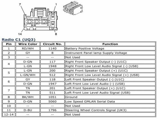
- Colors: Each wire is assigned a color code (e.g., RED, BLK, YEL, GRN). These codes are crucial for identifying specific wires in the harness. Common colors include Red (power), Black (ground), Yellow (constant power/memory), and various colors for speaker wires.
- Icons: Represent electronic components like resistors, capacitors, diodes, and connectors. Consult a key or legend on the diagram to understand the specific meaning of each icon.
- Connectors: Usually depicted as small squares or rectangles, indicating where wires plug into each other or into components. Connector numbers are often included for identification.
- Ground Symbols: Indicate where the wiring is grounded to the vehicle chassis.
It's imperative to match the colors exactly when working on the wiring, as using the wrong wire can cause damage to your electrical components.
How It Works: A Simplified View
The radio wiring system operates on a relatively straightforward principle:
- Power Supply: The radio receives power from the vehicle's battery through a fused circuit. Typically, there are two power wires: one providing constant power (for memory retention) and another providing switched power (activated when the ignition is turned on).
- Ground: A ground wire connects the radio to the vehicle's chassis, providing a return path for the electrical current.
- Signal Input: The radio receives audio signals from various sources, such as the antenna (for radio broadcasts), a CD player, or an auxiliary input.
- Audio Processing: The radio processes the audio signal, amplifying it (if there's no external amplifier) and sending it to the speakers.
- Speaker Output: The radio sends the amplified audio signal to the speakers through dedicated speaker wires. Each speaker has a positive (+) and negative (-) wire. Pay attention to polarity; reversing the polarity of speaker wires can negatively impact sound quality and stereo imaging.
Real-World Use: Basic Troubleshooting Tips
Here are some basic troubleshooting tips using the wiring diagram:
- No Power: Check the fuses related to the radio. Use a multimeter to verify that the radio is receiving power and ground. Trace the power and ground wires back to their source if necessary.
- Speaker Issues: If one or more speakers aren't working, check the speaker wires for damage or loose connections. Use a multimeter to test the speaker wires for continuity. You can also test the speaker itself with the multimeter, to check the speaker's resistance.
- Intermittent Problems: Loose connections or corroded terminals can cause intermittent issues. Inspect all connectors and terminals for corrosion. Clean or replace them as needed.
- Aftermarket Radio Problems: Ensure that the aftermarket radio is properly wired according to its instructions and the vehicle's wiring diagram. Use a wiring harness adapter to avoid cutting or modifying the factory wiring.
A simple test light can also be used to check for power to the radio. If a wire reads 12v, power is flowing through it.
Safety: Prioritize Protection
Working with automotive electrical systems can be dangerous. Here are some safety precautions:
- Disconnect the Battery: Always disconnect the negative (-) battery terminal before working on the electrical system to prevent shorts and electrical shocks.
- Use Appropriate Tools: Use insulated tools designed for automotive electrical work.
- Avoid Working in Wet Conditions: Water conducts electricity, increasing the risk of electric shock.
- Be Careful with Airbags: If you're working near airbags, be extremely careful not to damage the airbag wiring. Accidental airbag deployment can cause serious injury.
- Understand Wiring: Never guess when you do not know what you are working on.
The 2007 Chevrolet Silverado's radio wiring diagram is a valuable tool for any DIYer looking to understand, upgrade, or repair their audio system. By understanding the symbols, components, and basic principles, you can confidently tackle a wide range of audio-related projects. Remember to always prioritize safety and double-check your work to ensure a successful and trouble-free outcome. By understanding the wiring diagram, you can make informed decisions and avoid costly mistakes. Good luck!