2007 Chevy Silverado Radio Wiring Harness Diagram
Alright, let's dive into the 2007 Chevy Silverado radio wiring harness diagram. Whether you're upgrading your sound system, diagnosing a malfunctioning radio, or simply learning more about your truck's electrical system, understanding this diagram is crucial. This isn't just some abstract schematic; it's the roadmap to your audio experience and a critical component for maintaining your Silverado's functionality.
Purpose of the 2007 Chevy Silverado Radio Wiring Harness Diagram
The primary purpose of this diagram is to provide a visual representation of the electrical connections within the radio system. Think of it as a blueprint. It illustrates how the radio unit connects to the vehicle's power source, speakers, antenna, and other components. This is invaluable for:
- Troubleshooting: Pinpointing the source of audio issues like no sound, intermittent sound, or a completely dead radio.
- Installation: Safely and correctly installing aftermarket radios, amplifiers, or speakers.
- Repair: Identifying and repairing damaged wires or connectors in the harness.
- Modification: Making custom modifications to the audio system, such as adding subwoofers or integrating new technologies.
- Education: Learning about automotive electrical systems and how different components interact.
Without this diagram, you're essentially working blind, increasing the risk of damaging your vehicle's electrical system and potentially causing a fire hazard. Remember, automotive electrical systems are sensitive, and guessing is *never* a good idea.
Key Specs and Main Parts of the Wiring Harness
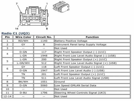
The 2007 Chevy Silverado radio wiring harness diagram outlines the connections for the factory-installed radio system. It typically covers the following key components and specifications:
- Power Supply: Includes the 12V constant (memory power) and 12V switched (ignition power) wires. These are essential for the radio to function and retain settings. Usually, the constant 12V is responsible for maintaining things like preset radio stations and clock settings.
- Ground Wire: Provides a return path for the electrical current, ensuring a complete circuit. A good, clean ground is absolutely critical for proper operation.
- Speaker Wires: These carry the audio signal from the radio to the speakers. The Silverado typically has four speaker channels: front left, front right, rear left, and rear right. Each speaker channel has a positive (+) and negative (-) wire.
- Antenna Wire: Connects the radio to the vehicle's antenna, allowing it to receive radio signals. Usually, this is a coaxial cable.
- Data Bus Wires (if applicable): Some radios communicate with the vehicle's computer (ECU or BCM) through a data bus, such as the CAN bus. These wires allow the radio to display information from the vehicle or control other functions.
- Remote Turn-On Wire (for amplifiers): A 12V signal wire that activates aftermarket amplifiers when the radio is turned on. This is *essential* if you are adding an external amplifier.
Important Note: There might be minor variations in the wiring depending on the specific trim level and options package of your Silverado. Always double-check the diagram against your vehicle's actual wiring to ensure accuracy.
Understanding the Symbols
The wiring diagram uses standard electrical symbols to represent different components and connections. Here's a breakdown of common symbols you'll encounter:
- Solid Lines: Represent wires. Thicker lines often indicate wires that carry higher current.
- Dashed Lines: May indicate shielding or a less critical connection.
- Circles: Often represent connection points or splices.
- Rectangles: Typically represent components like the radio unit itself, or modules such as an amplifier.
- Ground Symbol: Looks like an upside-down triangle or a series of horizontal lines decreasing in size. Indicates a connection to the vehicle's chassis ground.
- Wire Colors: Each wire is assigned a color code (e.g., RED, BLU, GRN, YEL). These colors are *critical* for identifying the correct wires in the harness. The diagram will usually include a key or legend that explains the color codes.
Color Codes: The color codes in the diagram are universally accepted within the automotive industry. Common color abbreviations include: BK (Black), RD (Red), WH (White), BL (Blue), GN (Green), YE (Yellow), OR (Orange), BN (Brown), VT (Violet). Some wires may have a primary color and a stripe (e.g., WH/BL means a white wire with a blue stripe). Pay close attention to both the primary color and the stripe when identifying wires. A multimeter is a vital tool for electrical testing.
How It Works: Tracing the Circuit
The radio wiring harness diagram illustrates the flow of electrical current through the audio system. Let's consider a simplified example:
- The 12V constant wire provides continuous power to the radio, allowing it to retain memory settings.
- The 12V switched wire provides power to the radio when the ignition is turned on.
- The ground wire completes the circuit, allowing current to flow back to the battery.
- When the radio is powered on, it sends an audio signal through the speaker wires to the speakers.
- The speakers convert the electrical signal into sound waves.
By tracing the circuit on the diagram, you can understand how each component interacts and identify potential points of failure. For example, if you're experiencing no sound from a particular speaker, you can trace the speaker wires back to the radio and check for breaks, loose connections, or a faulty speaker.
Real-World Use: Basic Troubleshooting
Here are a few basic troubleshooting scenarios where the wiring diagram can be invaluable:
- Radio Not Turning On: Check the 12V constant, 12V switched, and ground wires. Use a multimeter to verify that you're getting power to the radio and that the ground connection is solid.
- No Sound from One Speaker: Check the speaker wires for that speaker, both at the radio and at the speaker itself. Test the speaker with another audio source to rule out a faulty speaker.
- Interference or Static: Check the antenna wire and ground connections. A loose or corroded antenna wire can cause poor reception.
- Radio Loses Memory: The 12V constant wire may be disconnected or have a blown fuse.
Remember to always disconnect the negative terminal of the battery before working on the electrical system. This will prevent accidental shorts and potential damage. Before disconnecting, ensure that you know the code for your factory radio. Some radios will require a security code to reactivate after power loss.
Safety Precautions
Working with automotive electrical systems can be dangerous. Here are some crucial safety precautions:
- Disconnect the Battery: Always disconnect the negative terminal of the battery before working on the electrical system.
- Use Proper Tools: Use insulated tools and wear safety glasses.
- Avoid Working in Wet Conditions: Water conducts electricity, increasing the risk of electric shock.
- Identify Potentially Risky Components: Capacitors can store electrical charge even after the power is disconnected. Be careful when working around capacitors.
- Don't Modify Airbag Wiring: Airbag systems are extremely sensitive and potentially dangerous. Never attempt to modify or repair airbag wiring unless you are a qualified technician. Improper handling can cause accidental deployment.
- When in doubt, seek professional help: If you're not comfortable working on the electrical system, consult a qualified mechanic or audio installer.
Important: The Airbag system is very sensitive and can cause serious injury if handled incorrectly. Consult a professional when dealing with any airbag components.
We have the complete 2007 Chevy Silverado radio wiring harness diagram available for download. It will prove to be an invaluable asset for your audio upgrades, troubleshooting, and repairs. With the diagram in hand, you'll have the knowledge to tackle your audio projects with confidence and safety.