2007 Dodge Ram 2500 Fuse Box Diagram
Let's dive into the fuse box diagram for a 2007 Dodge Ram 2500. Understanding this diagram is crucial for a variety of reasons, from simple repairs to more complex modifications. Whether you're chasing down a faulty circuit, installing aftermarket accessories, or just trying to learn more about your truck's electrical system, this information is invaluable. This article assumes you have some basic mechanical and electrical knowledge. We’ll be covering the locations, functions, and how to interpret the symbols found on the diagram.
Purpose: Why Bother with a Fuse Box Diagram?
The fuse box diagram is essentially a roadmap for your truck's electrical system. Without it, troubleshooting electrical issues becomes a guessing game. Imagine trying to find a blown fuse among dozens without knowing which one controls a specific function like the power windows or headlights. The diagram provides a quick and accurate way to identify the correct fuse or relay, saving you time, frustration, and potential damage to your vehicle. Here are some key reasons why you'd want to familiarize yourself with this diagram:
- Troubleshooting Electrical Issues: Locating and replacing blown fuses is the most common use.
- Installing Aftermarket Accessories: Knowing which circuits are available allows for safe and proper integration of new components, like lighting, audio systems, or auxiliary power outlets.
- Understanding Your Vehicle's Electrical System: Gain a deeper understanding of how different systems are powered and protected.
- Preventing Further Damage: Incorrectly replacing a fuse with a higher amperage rating can overload the circuit and potentially cause a fire. The diagram ensures you use the correct replacement.
Key Specs and Main Parts of the Fuse Box
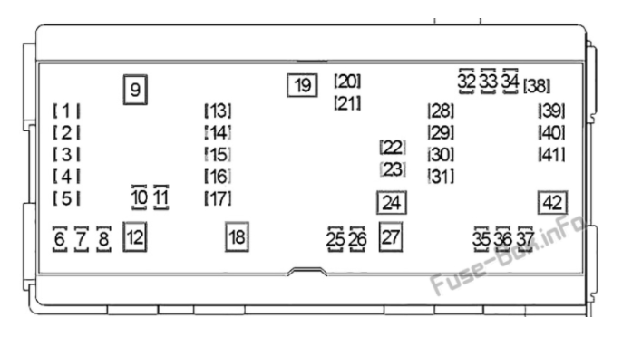
The 2007 Dodge Ram 2500 typically has two main fuse box locations. Identifying the correct location for your specific issue is the first step:
- Power Distribution Center (PDC): Located under the hood, usually near the battery. This houses the higher-amperage fuses and relays responsible for protecting major systems like the engine, transmission, and ABS. This is the primary fuse box you'll be working with.
- Integrated Power Module (IPM): This module contains both fuses and relays and integrates many of the trucks systems.
The PDC typically contains the following components:
- Fuses: These are designed to protect circuits from overcurrent. They contain a thin wire that melts and breaks the circuit if the current exceeds a specified level. Fuses are rated in amperes (amps), which indicate the maximum current they can safely carry.
- Relays: These are electromechanical switches that use a small current to control a larger current. They are used to switch high-power circuits on and off, such as headlights, starter motors, and cooling fans. Relays are often used when the control switch is located far from the device it controls.
- Circuit Breakers: Similar to fuses, circuit breakers protect circuits from overcurrent. However, instead of melting, they trip and can be reset. They are typically used for circuits that may experience temporary overloads, such as power windows or door locks.
- Wiring Harness Connectors: These provide the electrical connections to and from the fuse box.
Understanding the Fuse Box Diagram Symbols
The fuse box diagram uses a variety of symbols to represent different components and their functions. Let's break down some of the common ones:
Lines and Colors:
- Solid Lines: Indicate a direct electrical connection.
- Dashed Lines: Indicate a connection that may be optional or only present in certain configurations.
- Different Colors: While not always present in all diagrams, different colored lines often represent different wire gauges or different types of signals (e.g., power, ground, signal). You'll need to refer to the wiring diagram, separate from the fuse box diagram, for full color-coding details.
Icons and Abbreviations:
- Fuse Symbol: Typically a zig-zag line enclosed in a rectangle.
- Relay Symbol: A coil representing the relay's electromagnet, connected to a switch representing the contacts.
- Various Abbreviations: These are used to identify the function of each fuse or relay. Common examples include:
- PCM: Powertrain Control Module (engine computer)
- ABS: Anti-lock Braking System
- IGN: Ignition
- PWR WDO: Power Window
- H/LP: Headlamp
It is important to know the difference between a schematic and a wiring diagram. Schematics represent the logic of a circuit. Wiring diagrams represent the physical connections of the circuit.
How the Fuse Box Works
The fuse box is the central distribution point for electrical power in your truck. Power from the battery is fed into the fuse box, and then distributed to various circuits through fuses and relays. Each circuit is protected by a fuse of the appropriate amperage rating. If a fault occurs in a circuit, such as a short circuit (a low-resistance path to ground), the current will increase dramatically. This high current will cause the fuse to blow, interrupting the circuit and preventing damage to other components. Relays, on the other hand, are used to control high-current circuits with a low-current signal. For example, the headlight switch may only carry a small current, but it controls a relay that switches on the high-current headlights.
Real-World Use: Basic Troubleshooting Tips
Here's a step-by-step approach to troubleshooting electrical issues using the fuse box diagram:
- Identify the Problem: Determine which system or component is not working.
- Consult the Diagram: Locate the fuse or relay that corresponds to the affected system. The fuse box diagram will be inside the lid of the fuse box, or printed in your owner's manual.
- Inspect the Fuse: Visually inspect the fuse. A blown fuse will typically have a broken filament. You can also use a multimeter to test the fuse for continuity (a low resistance reading indicates a good fuse).
- Replace the Fuse: If the fuse is blown, replace it with a fuse of the same amperage rating. Never use a fuse with a higher rating, as this can overload the circuit and cause a fire.
- Test the System: After replacing the fuse, test the system to see if it is working properly. If the fuse blows again immediately, there is likely a short circuit or other problem in the circuit that needs further investigation.
- Check the Relay (If Applicable): If the fuse is good, but the system is still not working, the relay may be faulty. You can test the relay by swapping it with a known good relay, or by using a multimeter to check its operation.
Safety: Identifying Risky Components
Working with electrical systems can be dangerous. Always disconnect the negative battery cable before working on the fuse box to prevent accidental shorts and electrical shocks. Some components, such as the PCM and ABS module, are sensitive to static electricity. Handle these components with care and use proper grounding techniques. Never attempt to bypass a fuse or relay with a wire or other conductive material. This can create a fire hazard and cause serious damage to your vehicle.
Be particularly cautious when working with circuits related to the airbag system. Accidental activation of the airbags can cause serious injury. Consult a qualified technician if you are not comfortable working with these systems.
Finally, remember that the information here provides a general guide. Specific wiring and fuse assignments can vary slightly depending on the model year, trim level, and options installed on your 2007 Dodge Ram 2500. Always refer to the specific fuse box diagram for your vehicle.
We have a downloadable PDF version of the 2007 Dodge Ram 2500 Fuse Box Diagram available. This will give you a high-resolution copy to print out and use in your garage, making your troubleshooting tasks much easier.