
2007 Ford Mustang Gt Fuse Box Diagram
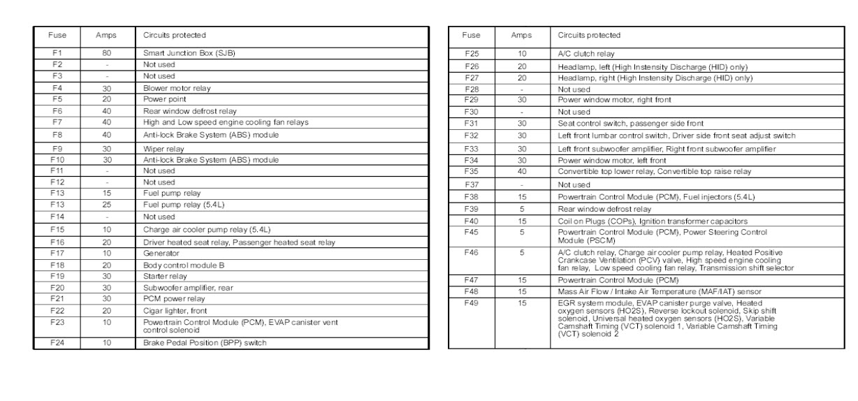
The 2007 Ford Mustang GT, a modern classic, is beloved by enthusiasts for its blend of retro styling and V8 power. But even the most well-maintained Mustang can experience electrical issues. Understanding the fuse box diagram is crucial for diagnosing and resolving these problems, preventing minor glitches from escalating into costly repairs. This article provides an in-depth guide to the 2007 Mustang GT fuse box diagram, offering insights for intermediate car owners, modders, and DIY mechanics.
Purpose of the Fuse Box Diagram
The fuse box diagram serves as a roadmap for the electrical system. It's essential for:
- Troubleshooting Electrical Problems: Identifying blown fuses associated with specific circuits, saving time and money compared to guesswork.
- Performing Electrical Modifications: Safely tapping into circuits for aftermarket accessories like amplifiers, lighting, or performance upgrades.
- Understanding Vehicle Systems: Gaining a deeper understanding of how the car's electrical components are interconnected.
- Preventing Further Damage: Quickly addressing electrical faults before they damage sensitive electronic modules.
Without a clear understanding of the fuse box layout, you risk incorrect diagnoses, accidental short circuits, and potentially irreversible damage to your Mustang's electrical system.
Key Specs and Main Parts
The 2007 Mustang GT has two primary fuse boxes:
Battery Junction Box (BJB)
Located in the engine compartment, typically on the driver's side. The BJB houses high-amperage fuses and relays that protect critical systems like the starter motor, alternator, and ABS (Anti-lock Braking System). It also contains fuses for the headlights, windshield wipers, and other essential components. The BJB is the main power distribution center for the vehicle.
Smart Junction Box (SJB)
Located inside the passenger compartment, often under the dashboard on the driver's side. The SJB controls lower-amperage circuits responsible for interior functions like the radio, power windows, door locks, instrument cluster, and lighting. The SJB often integrates with the car's central computer and body control module (BCM). Some functions are controlled by solid state relays inside the SJB, meaning traditional replacement is impossible.
Key Specs to consider:
- Fuse Ampere Rating: Each fuse is rated for a specific amperage (e.g., 5A, 10A, 15A, 20A, 30A). Using a fuse with a higher amperage rating than specified can damage the circuit it protects.
- Fuse Type: Fuses come in various types, including blade fuses (ATO/ATC), mini blade fuses, and cartridge fuses. Ensure you use the correct type for replacement.
- Relay Type: Relays are electromechanical switches that control high-current circuits using a low-current signal. Relays are essential for functions like starting, fuel pump operation, and air conditioning.
- Wiring Gauge: The thickness of the wiring (gauge) is crucial. Thicker wiring can handle more current. The fuse rating is designed to protect the wire itself from overheating and causing a fire.
Symbols and Diagram Interpretation
Fuse box diagrams use standardized symbols to represent electrical components and connections. Understanding these symbols is vital for accurate troubleshooting.
Lines and Colors
- Solid Lines: Represent direct electrical connections between components.
- Dashed Lines: May indicate a ground connection or a less direct connection, often through a harness.
- Colors: Different colored wires represent different circuits or functions. The diagram may include a wire color code chart. For example, a red wire often indicates a power source.
Icons and Abbreviations
- Fuse Symbol: A zig-zag line enclosed in a rectangle. The amperage rating is usually indicated next to the symbol.
- Relay Symbol: A coil of wire representing the relay's electromagnet and a switch representing the contacts.
- Ground Symbol: A series of downward-pointing lines, indicating a connection to the vehicle's chassis (ground).
- Common Abbreviations: Common abbreviations you'll find are ACC (accessory), IGN (ignition), PWR (power), GND (ground), and ECM (engine control module).
Important Note: Fuse box diagrams can vary slightly depending on the vehicle's specific options and production date. Always consult the diagram specific to your 2007 Mustang GT, preferably from the owner's manual or a reputable service manual.
How It Works
The fuse box acts as a central distribution point for electrical power. When you turn on the ignition, the battery sends power to the various circuits through the fuse box. Each circuit is protected by a fuse, which is a sacrificial device designed to blow (open the circuit) if the current exceeds a safe level.
When a fuse blows, it indicates that there's an overcurrent situation in the circuit. This can be caused by:
- Short Circuit: A direct connection between a power wire and ground, bypassing the intended load (e.g., a frayed wire touching the chassis).
- Overload: Too much current being drawn by a component (e.g., a faulty motor drawing excessive current).
- Component Failure: A failed component causing a surge in current (e.g., a shorted-out electronic module).
Relays act as electrically controlled switches. The computer (PCM or BCM) will send a small electrical current that energizes the relay's internal coil, which closes the switch and allows a higher current to flow through the circuit. This enables the computer to control high-current components with a low-current signal.
Real-World Use: Basic Troubleshooting Tips
Here's a basic troubleshooting process using the fuse box diagram:
- Identify the Problem: Determine which electrical function is not working (e.g., headlights, radio, power windows).
- Consult the Diagram: Locate the fuse or relay associated with the malfunctioning function in the fuse box diagram.
- Inspect the Fuse: Visually inspect the fuse. If the wire inside the fuse is broken or blackened, the fuse is blown. A multimeter can also be used to verify continuity.
- Replace the Fuse: Replace the blown fuse with a new fuse of the exact same amperage rating.
- Test the Circuit: After replacing the fuse, test the affected function to see if it's working.
- If the Fuse Blows Again: If the fuse blows again immediately or shortly after replacement, there's a persistent short circuit or overload in the circuit. Further diagnostics are required to pinpoint the source of the problem. This could involve checking wiring harnesses, connectors, and components.
Example: Your headlights are not working. You consult the BJB fuse box diagram and find that fuse #23 (20A) is responsible for the headlights. You inspect fuse #23 and find that it's blown. You replace it with a new 20A fuse, and the headlights start working again. Problem solved!
Safety Considerations
Working with automotive electrical systems can be dangerous. Here are some safety precautions:
- Disconnect the Battery: Always disconnect the negative battery terminal before working on the electrical system to prevent accidental short circuits and shocks.
- Use Proper Tools: Use insulated tools designed for automotive electrical work.
- Never Bypass Fuses: Never bypass a fuse with a wire or other conductive material. This eliminates the circuit protection and can lead to a fire or severe damage.
- High-Amperage Circuits: Be extremely cautious when working with high-amperage circuits in the BJB, such as the starter motor and alternator circuits. These circuits can deliver a significant electrical shock.
- Airbags and SRS: The Supplementary Restraint System (SRS), including airbags, has dedicated fuses. Improper handling of these circuits can lead to accidental airbag deployment, which can cause serious injury. If you are unsure, seek professional assistance.
Accessing the Diagram
We have a high-resolution, printable PDF of the 2007 Ford Mustang GT fuse box diagram available for download. This diagram includes both the BJB and SJB layouts, with detailed fuse and relay assignments. Click the link below to download the diagram and keep it handy for all your future electrical troubleshooting needs. Remember, having this diagram readily available can save you time, money, and potential headaches down the road. Keep it in your glovebox or save it to your phone for easy access whenever you need it.
[Download Link Here - Replace with actual link]