2007 Gmc Sierra Radio Wiring Harness
The 2007 GMC Sierra radio wiring harness is the unsung hero of your truck's entertainment system. It’s the intricate web of wires that connects your radio (or aftermarket head unit) to the vehicle's electrical system, speakers, and other components. Understanding this harness is crucial for a variety of reasons, from basic radio replacement and speaker upgrades to more complex modifications involving amplifiers and other aftermarket devices. Without a grasp of its function and wiring diagram, you're essentially working blind, which can lead to damaged components, frustrating troubleshooting, and potentially hazardous electrical issues.
Purpose and Importance
Why should you care about this diagram? Well, consider these scenarios:
- Radio Replacement: The most common reason. Swapping out your factory radio for a newer model or an aftermarket head unit requires understanding the harness to connect the new unit properly.
- Speaker Upgrades: Upgrading your speakers often involves tapping into the existing speaker wires, and knowing which wire goes to which speaker is essential.
- Amplifier Installation: Adding an amplifier requires signal input from the radio and power from the vehicle's electrical system, both of which are accessed through the harness.
- Troubleshooting: If your radio isn't working correctly, understanding the harness can help you isolate the problem, whether it's a faulty ground connection, a blown fuse, or a damaged wire.
- Learning and Modification: For anyone interested in automotive electrical systems, understanding the radio wiring harness is a great starting point for learning about how these systems work. You could even use this knowledge to add things like a backup camera or integrate custom controls.
Key Specs and Main Parts
The 2007 GMC Sierra's radio wiring harness isn't just one big plug; it's typically a series of connectors and individual wires, each with a specific function. Here's a breakdown of the key components and typical wire functions:
Power Wires
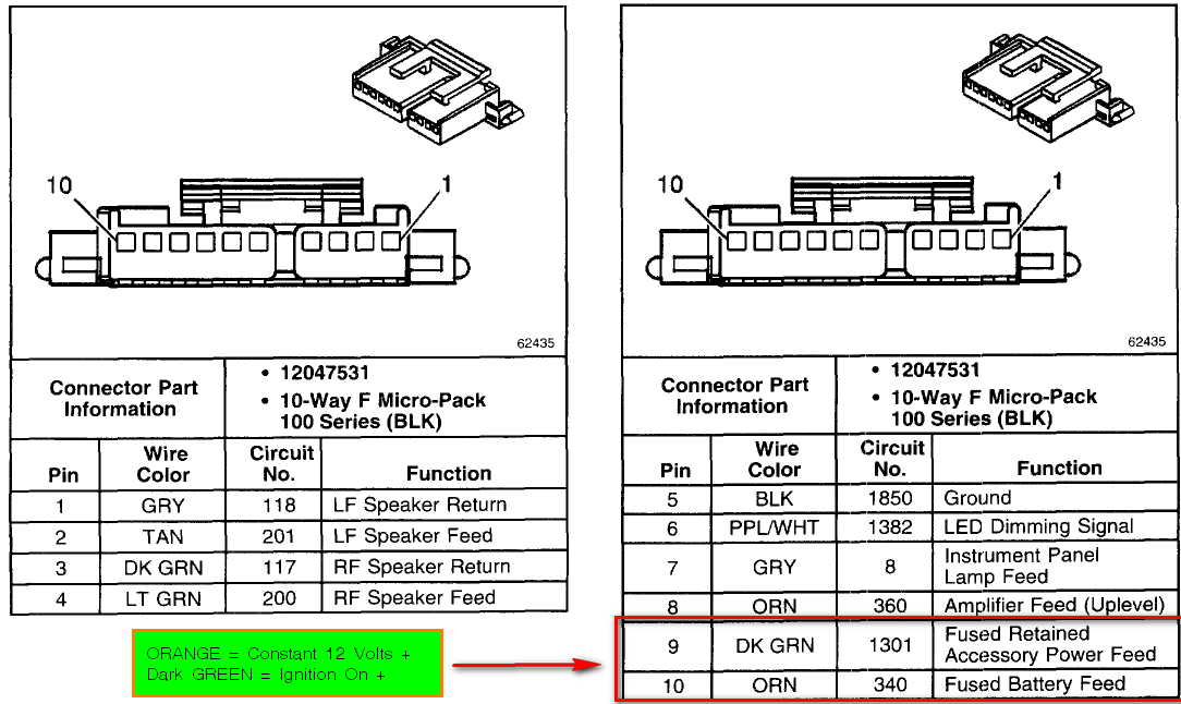
- Constant 12V (Battery): Provides a constant power source to the radio, even when the ignition is off. This wire is usually yellow or orange. It's essential for the radio's memory functions (e.g., station presets).
- Switched 12V (Ignition): Provides power to the radio only when the ignition is turned on. This wire is often red.
- Ground: Completes the electrical circuit and provides a reference point for voltage. Usually black or brown. A solid ground connection is absolutely crucial for proper operation.
Speaker Wires
These wires carry the audio signal from the radio to the speakers. Each speaker has a positive (+) and a negative (-) wire. The colors and functions will vary, but here's a general idea:
- Front Left (+/-): Two wires for the front left speaker.
- Front Right (+/-): Two wires for the front right speaker.
- Rear Left (+/-): Two wires for the rear left speaker.
- Rear Right (+/-): Two wires for the rear right speaker.
Note: Some models might have separate tweeters or a subwoofer, which would have their own dedicated wires.
Other Important Wires
- Antenna Wire: Connects the radio to the antenna. Typically a coaxial cable.
- Illumination Wire: Dims the radio display when the headlights are turned on. Usually orange or white/blue stripe.
- Remote Turn-On (Amplifier): A 12V signal that turns on an aftermarket amplifier when the radio is turned on. Often blue.
- Data Bus Wires (CAN Bus): Newer vehicles use a Controller Area Network (CAN) bus system for communication between different modules. These wires may be present in the radio harness for functions like steering wheel controls or vehicle information display. Understanding the CAN bus requires more advanced knowledge and specialized tools.
Symbols – Understanding the Wiring Diagram
A wiring diagram is a schematic representation of the electrical circuits in your vehicle. Learning to read it is essential for safe and accurate wiring.
- Lines: Represent wires. Solid lines indicate a direct connection, while dashed lines might indicate a shielded wire or a connection through a connector.
- Colors: Wires are often color-coded, and the diagram will use abbreviations for these colors (e.g., BLK for black, RED for red, GRN for green, YEL for yellow, BLU for blue).
- Connectors: Represented by various symbols, like circles, squares, or rectangles, often with numbers or letters to identify the specific pin or terminal.
- Components: Radios, speakers, fuses, and other electrical components are represented by standardized symbols.
A good wiring diagram will include a key or legend explaining the symbols and color codes used.
How It Works
The radio wiring harness acts as a central distribution point for power, ground, and audio signals. The constant 12V power keeps the radio's memory alive, while the switched 12V power turns the radio on and off with the ignition. The ground wire provides a stable reference point for voltage. The speaker wires carry the amplified audio signal to the speakers, allowing you to hear music, podcasts, or the news. The antenna wire receives radio signals. Other wires, like the illumination and remote turn-on wires, provide additional functionality and control.
The modern harnesses may interface with the vehicle's computer system (ECU) using CAN bus. The CAN bus allows components to share information. If you are replacing a factory radio with an aftermarket unit, you likely will need a CAN bus adapter to retain features like steering wheel controls and OnStar functionality.
Real-World Use – Basic Troubleshooting Tips
Here are a few basic troubleshooting tips for dealing with your radio wiring harness:
- No Power: Check the fuses first! Use a multimeter to verify that you have both constant and switched 12V power at the harness. Also, make sure the ground connection is solid. A loose or corroded ground is a common culprit.
- No Sound: Check the speaker wires for continuity using a multimeter. Make sure the speaker wires are not shorted to ground. If you are using an aftermarket amplifier, check the remote turn-on wire.
- Distorted Sound: Check the speaker wires for damage or loose connections. Make sure the speakers are properly wired (positive to positive, negative to negative).
- Interference: Make sure the antenna wire is properly connected and not damaged. Check for any sources of electrical interference, such as a faulty alternator or ignition system.
- Steering Wheel Controls Not Working: If you've installed an aftermarket radio and your steering wheel controls are not working, you likely need a CAN bus adapter or a steering wheel control interface.
When troubleshooting, it’s crucial to use a multimeter and test light to check for voltage, continuity, and shorts. Always disconnect the battery before working on the electrical system to avoid accidental shorts or shocks.
Safety – Highlight Risky Components
Working with automotive electrical systems can be dangerous. The most significant risk is electrical shock. Always disconnect the negative terminal of the battery before working on the wiring harness. Be particularly careful when working with the constant 12V power wire, as it can cause a short circuit if it comes into contact with the vehicle's chassis. Never cut or splice wires without first disconnecting the battery. And always use proper wiring techniques, such as soldering and heat shrinking, to ensure secure and reliable connections.
Also, be aware of the airbag system. Some wiring harnesses may run near airbag sensors or modules. Avoid tampering with these wires, as it could inadvertently trigger the airbags. When in doubt, consult a qualified professional.
Download the Diagram
Having the correct wiring diagram for your specific 2007 GMC Sierra model is essential for safe and accurate wiring. We have the 2007 GMC Sierra radio wiring diagram file available for you to download. This diagram will provide you with the specific wire colors and functions for your truck, making your radio replacement or upgrade project much easier and safer.