
2007 Honda Civic Stereo Wiring Diagram
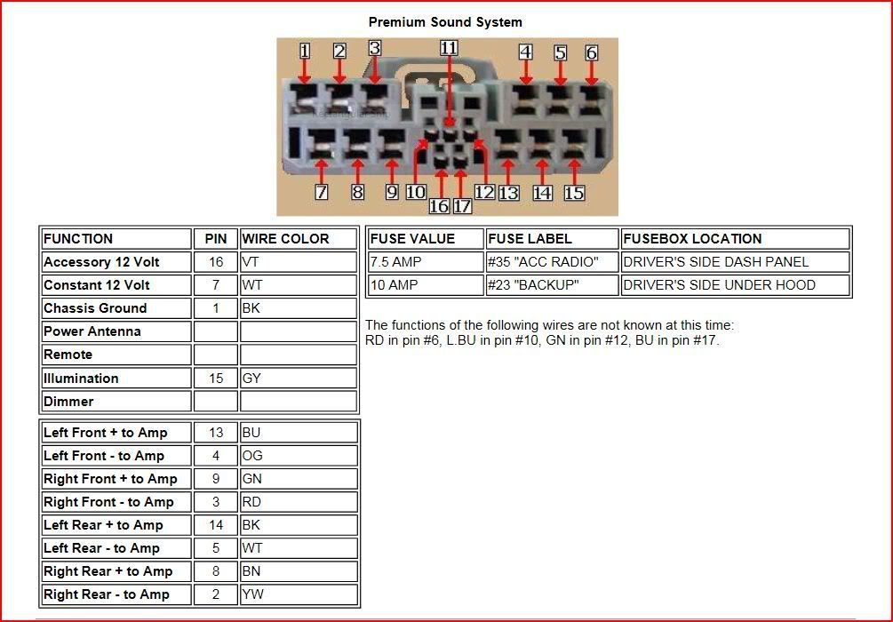
The 2007 Honda Civic is a popular car, known for its reliability. However, even reliable cars sometimes need their audio systems tweaked, repaired, or upgraded. Understanding the stereo wiring diagram for your 2007 Civic is crucial whether you're replacing a blown speaker, installing a new head unit, or just trying to diagnose a buzzing sound. This article will break down the diagram, explain its key components, and provide practical advice for using it safely and effectively.
Purpose of the Stereo Wiring Diagram
A stereo wiring diagram is essentially a roadmap of your car's audio system. It shows how all the different components are connected electrically. This information is invaluable for several reasons:
- Repairs: If a speaker isn't working, or your head unit suddenly dies, the diagram helps you trace the wires to identify the faulty connection or component.
- Upgrades: When installing aftermarket speakers, subwoofers, amplifiers, or a new head unit, the diagram tells you where to tap into the existing wiring, ensuring proper connections and preventing damage to your car's electrical system.
- Troubleshooting: Electrical gremlins in your audio system can be frustrating. The diagram allows you to systematically check continuity, voltage, and ground connections to pinpoint the source of the problem.
- Education: Even if you don't plan on performing any work yourself, understanding the diagram gives you a deeper knowledge of your car's systems and empowers you to communicate more effectively with a mechanic.
Key Specs and Main Parts
The 2007 Honda Civic stereo system, in its factory configuration, typically includes the following components. Variations may exist based on trim level (DX, LX, EX, etc.) and whether or not it's equipped with the factory navigation system.
- Head Unit (Radio/Receiver): This is the control center of the audio system. It houses the radio tuner, CD player (if equipped), amplifier, and various input/output connections.
- Speakers: The Civic usually features speakers in the front doors and sometimes in the rear deck or rear doors, depending on the trim.
- Wiring Harnesses: These bundles of wires connect the head unit to the speakers, power source, ground, and other components. They are typically color-coded for easy identification.
- Antenna: Receives radio signals.
- Amplifier (Optional): Some higher trim levels might include a factory amplifier to boost the audio signal. Location varies.
The wiring diagram will specify the gauge (thickness) of the wires used. Thicker wires are used for higher current applications, such as power and ground, while thinner wires are used for signal transmission to the speakers.
Symbols: Lines, Colors, and Icons
Understanding the symbols used in the wiring diagram is essential for interpreting it correctly.
- Lines: Solid lines represent wires. Dashed lines may indicate shielding or less critical connections. The thickness of the line doesn't necessarily correlate with wire gauge.
- Colors: Each wire is assigned a specific color code (e.g., BLU for blue, RED for red, GRN for green, YEL for yellow, WHT for white, BLK for black). This is critical for identifying the correct wire in your car. Combinations are also used (e.g., RED/WHT for red with a white stripe). Always double-check the color coding in your car as variations can occur.
- Icons:
- Ground Symbol (often a triangle): Indicates a connection to the vehicle's chassis, providing a return path for the current. A good ground is crucial for proper operation.
- Fuse Symbol: Represents a fuse, which protects the circuit from overcurrent.
- Connector Symbol (usually a rectangle): Shows where two wiring harnesses connect.
- Speaker Symbol: Indicates a speaker.
The diagram will also include alphanumeric codes that identify specific connectors and circuits. For example, a code like "A23" might refer to a specific connector on the head unit.
How It Works: Basic Circuit Flow
The stereo system works by receiving power from the car's battery, typically through the ignition switch. When the ignition is turned on, power flows to the head unit. The head unit processes audio signals from various sources (radio, CD, etc.) and amplifies them. These amplified signals are then sent to the speakers, which convert the electrical signals into sound waves.
The system also requires a good ground connection. This provides a return path for the current, completing the circuit. A poor ground can cause a variety of problems, including weak audio, distortion, and even damage to the components.
Real-World Use: Basic Troubleshooting Tips
Here are a few common troubleshooting scenarios where the wiring diagram can be helpful:
- No Power to Head Unit: Check the fuses related to the audio system. The diagram will show you their location and amperage. If the fuse is blown, replace it with one of the same amperage. If it blows again immediately, there's likely a short circuit in the wiring. Use the diagram to trace the power wire and look for any damage or exposed conductors.
- One Speaker Not Working: Use a multimeter to check for continuity between the head unit and the speaker. The diagram will tell you which wires to test. If there's no continuity, there's a break in the wire. Also, check the speaker itself using the multimeter (set to Ohms). If you get an open circuit (OL) it's likely the speaker is bad.
- Buzzing or Hissing Sound: This can be caused by a poor ground connection. Use the diagram to locate the ground wires and ensure they are securely connected to the vehicle's chassis. Clean any corrosion from the ground connections.
When troubleshooting, always start with the simplest checks first (fuses, connections) before moving on to more complex tests. Use the wiring diagram to guide your testing and avoid unnecessary disconnections.
Safety: Highlight Risky Components
Working with automotive electrical systems can be dangerous if you're not careful. Here are a few safety precautions to keep in mind:
- Disconnect the Battery: Before working on any electrical components, disconnect the negative terminal of the battery to prevent accidental shorts or shocks.
- Work in a Well-Lit Area: Good lighting is essential for seeing what you're doing and avoiding mistakes.
- Use Proper Tools: Use insulated tools designed for automotive electrical work.
- Identify Airbag Wiring: Be extremely careful when working near airbag wiring. Accidental deployment of an airbag can cause serious injury. Consult the wiring diagram and avoid disturbing any airbag-related components unless you are specifically trained to do so. The diagram will usually have warnings near these components.
- Fuses are Important: Never replace a fuse with one of a higher amperage rating. This can overload the circuit and cause a fire.
Warning: The stereo system contains components powered by the car's electrical system. Improper handling can lead to electrical shock, fire, or damage to your vehicle. If you are not comfortable working with electrical systems, consult a qualified professional.
We have access to the full 2007 Honda Civic stereo wiring diagram file, with detailed color-coding and connector locations. This will allow you to properly diagnose your audio system. You can download the diagram to get started on your repair project.