2007 Honda Crv Front End Suspension Diagram Exploded View
Alright, let's dive into the 2007 Honda CR-V's front suspension. This guide, complete with an exploded view diagram (which you can download – we've got that for you!), will be your roadmap for understanding, maintaining, or even upgrading the suspension system on your trusty CR-V. Whether you’re tackling a worn-out ball joint, diagnosing a clunking noise, or just expanding your automotive knowledge, a solid understanding of the front suspension is crucial.
Purpose of Understanding the Diagram
Why bother with an exploded view diagram? Simple: it's your best friend when it comes to any kind of suspension work. It allows you to:
- Identify parts accurately: No more guessing names or ordering the wrong components.
- Understand assembly order: Crucial for reassembly, preventing mistakes and ensuring proper function.
- Troubleshoot problems: Seeing how components interact can reveal the root cause of issues.
- Plan repairs: Knowing the scope of a job and the parts required saves time and money.
- Customize and upgrade: Want to lower your CR-V or install stiffer springs? Understanding the stock setup is the first step.
- Learn the system: Deepen your understanding of automotive engineering, which can be very satisfying.
Think of this diagram as the IKEA instruction manual for your CR-V's front end. It breaks down a complex system into manageable, understandable pieces.
Key Specs and Main Parts
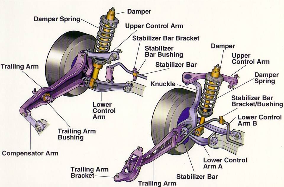
The 2007 CR-V utilizes a MacPherson strut front suspension. This is a common design, but let's break down the key components visible in the exploded view diagram:
- Strut Assembly: The heart of the system. This includes the shock absorber (damper), coil spring, and strut mount. The shock absorber controls the spring's oscillations, preventing excessive bouncing. The coil spring supports the vehicle's weight and provides ride comfort. The strut mount connects the strut assembly to the vehicle's body.
- Lower Control Arm: A crucial link connecting the steering knuckle/hub to the vehicle's frame. It allows the wheel to move up and down while maintaining its position. It has bushings that allow for controlled movement and absorb vibrations.
- Steering Knuckle (Hub Assembly): This component houses the wheel bearing and provides a mounting point for the brake caliper and steering linkage.
- Ball Joints: Spherical bearings that connect the control arm to the steering knuckle. They allow for smooth steering and suspension movement. There's usually a lower ball joint that connects to the lower control arm.
- Tie Rods (Inner and Outer): Part of the steering system, connecting the steering rack to the steering knuckle. They translate the steering wheel's motion into turning the wheels. The inner tie rod connects to the steering rack, while the outer tie rod connects to the steering knuckle.
- Sway Bar (Stabilizer Bar): Connects the left and right sides of the suspension. Its purpose is to reduce body roll during cornering. It does this by transferring force from one side of the suspension to the other. It's attached to the suspension with sway bar links and bushings.
- Sway Bar Links: Connect the sway bar to the strut assembly or control arm. They are responsible for transferring the sway bar's twisting force to the suspension components.
- Brake Caliper and Rotor: While technically part of the braking system, they are directly connected to the steering knuckle and must be removed for many suspension repairs.
- Wheel Bearing: Located inside the hub assembly, allowing the wheel to rotate smoothly.
Key Specs (General): While specific specs vary slightly year-to-year, here are some important figures to keep in mind. Refer to your CR-V's service manual for the precise values:
Torque Specifications: Critical for proper component installation. Always use a torque wrench and follow the manufacturer's recommendations. Lower control arm bolts, strut mount bolts, and ball joint nuts are particularly important.
Alignment Angles: Camber, caster, and toe are crucial for tire wear and handling. After any suspension work, a wheel alignment is highly recommended.
Spring Rates: Measured in lbs/inch or N/mm, determines the stiffness of the springs. Changing spring rates can significantly affect ride quality and handling.
Symbols and Diagram Conventions
Exploded view diagrams use a standardized set of symbols to represent different components and their relationships. Here's a breakdown of common symbols:
- Lines: Solid lines typically indicate the outline of a component. Dashed lines may represent hidden parts or pathways.
- Arrows: Show the direction of force or movement. They can also indicate the order of assembly or disassembly.
- Numbers/Letters: Each part in the diagram is typically assigned a number or letter, which corresponds to a parts list. This makes it easy to identify and order specific components.
- Exploded View: Parts are shown slightly separated from each other to illustrate their relationship and assembly order.
- Fasteners: Bolts, nuts, washers, and clips are usually represented with simplified symbols. The diagram should indicate the size and type of fastener required.
- Colors: In some diagrams, colors might be used to differentiate between materials (e.g., rubber bushings vs. metal components). However, many diagrams are black and white.
How It Works: A Simplified Explanation
The front suspension's primary job is to isolate the vehicle's body from road imperfections, providing a comfortable ride and maintaining tire contact with the road. Here's how it achieves this:
- The Wheel Encounters a Bump: The tire absorbs some of the impact, but the remaining force is transmitted to the steering knuckle.
- The Strut Compresses: The coil spring in the strut compresses, absorbing the upward force. The shock absorber dampens the spring's oscillation, preventing it from bouncing excessively.
- The Lower Control Arm Pivots: The lower control arm pivots on its bushings, allowing the wheel to move up and down while maintaining its position relative to the vehicle.
- The Ball Joints Articulate: The ball joints allow the steering knuckle to move freely, accommodating the suspension's movement and steering inputs.
- The Sway Bar Resists Body Roll: During cornering, the sway bar twists, transferring force from the outside wheel to the inside wheel, reducing body lean and improving stability.
Real-World Use: Basic Troubleshooting Tips
Here are some common front suspension problems and how the exploded view diagram can help with diagnosis:
- Clunking Noise: Could be worn ball joints, tie rod ends, sway bar links, or strut mounts. Use the diagram to inspect these components for play or damage.
- Squeaking Noise: Often caused by dry or worn-out bushings in the control arms or sway bar. The diagram helps you locate and identify these bushings.
- Wandering Steering: May indicate worn tie rod ends, ball joints, or a loose steering rack. Use the diagram to check for excessive play in these components.
- Uneven Tire Wear: Often a sign of misaligned suspension. After any suspension work, get a wheel alignment.
- Bouncing Ride: Worn shock absorbers are a likely culprit. The diagram will help you locate and replace them.
Safety Considerations
Suspension work can be dangerous if not performed correctly. Here are some critical safety precautions:
- Spring Compression: Coil springs are under immense pressure and can cause serious injury if released suddenly. Always use a proper spring compressor to safely compress and decompress coil springs. This is one of the most dangerous parts of suspension work. If you are not comfortable with this, leave it to a professional.
- Support the Vehicle Properly: Never work under a vehicle supported only by a jack. Use sturdy jack stands placed on designated support points.
- Disconnect the Battery: Disconnecting the negative battery terminal can prevent accidental electrical shocks or damage to electronic components.
- Wear Safety Glasses: Protect your eyes from flying debris and chemicals.
- Torque Specifications: Always tighten fasteners to the specified torque. Over-tightening can damage components, while under-tightening can lead to failure.
- Brake Lines: Be extremely careful when working near brake lines. Damaging a brake line can result in brake failure.
Always consult your vehicle's service manual for specific instructions and safety precautions.
Conclusion
Understanding the 2007 Honda CR-V's front suspension is a valuable skill for any DIY mechanic or car enthusiast. This guide, along with the exploded view diagram (which, remember, you can download), provides a solid foundation for tackling suspension repairs, upgrades, or simply expanding your automotive knowledge. Remember to prioritize safety and always consult your vehicle's service manual for specific instructions. Good luck, and happy wrenching!