
2007 Honda Ridgeline Fuse Box Diagram
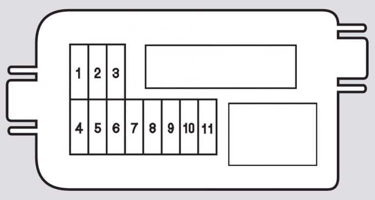
Let's dive deep into the fuse box diagram for your 2007 Honda Ridgeline. Understanding this diagram is invaluable, not just for replacing a blown fuse, but also for diagnostics, troubleshooting electrical problems, and even for safely adding aftermarket accessories. Think of it as the electrical roadmap to your truck. Whether you're an experienced DIYer or just starting to tackle more complex car projects, knowing your way around the fuse boxes will save you time, money, and potential headaches.
Purpose of the 2007 Honda Ridgeline Fuse Box Diagram
The fuse box diagram serves several critical purposes:
- Troubleshooting Electrical Issues: When an electrical component stops working – like a power window, a taillight, or the radio – the fuse box is the first place you should check. The diagram helps you identify the correct fuse associated with that component.
- Preventing Further Damage: A blown fuse indicates an overcurrent situation. Replacing it with the correct amperage fuse helps protect sensitive electrical components from damage due to shorts or surges.
- Adding Aftermarket Accessories: If you're installing accessories like a new stereo, auxiliary lighting, or a trailer brake controller, you'll need to know where to tap into the electrical system safely. The diagram guides you to appropriate fuse locations and circuit protection.
- Understanding the Electrical System: Studying the diagram gives you a basic understanding of how the electrical system is organized and how different components are interconnected.
Key Specs and Main Parts
The 2007 Honda Ridgeline has *two* main fuse boxes:
- Under-Hood Fuse Box: Located in the engine compartment, usually near the battery. This box houses fuses and relays for high-current circuits like the headlights, starter motor, ABS, and engine management system. These components generally require higher amperage protection.
- Under-Dash Fuse Box: Situated inside the cabin, typically on the driver's side, often behind a small access panel. This box contains fuses for lower-current circuits like the radio, interior lights, power windows, and various electronic modules.
Key Specifications to Consider:
- Fuse Amperage: Each fuse is rated for a specific amperage (measured in amps, abbreviated as "A"). Using a fuse with a higher amperage than specified can be extremely dangerous, as it can allow too much current to flow and potentially cause a fire. Always replace a blown fuse with one of the *exact* same amperage.
- Fuse Type: The Ridgeline primarily uses blade-type fuses (also called spade fuses), which come in various sizes (e.g., Mini, ATO/ATC, Maxi). The diagram will often indicate the fuse type for each location, or you can visually match the blown fuse.
- Relays: Relays are electromechanical switches that control high-current circuits using a low-current signal. They are also typically housed in the under-hood fuse box. Understanding their function is critical for diagnosing problems with components like the fuel pump, horn, or air conditioning compressor.
Symbols – Explaining Lines, Colors, and Icons
The fuse box diagram uses a series of symbols and abbreviations to represent different components and circuits. Understanding these is essential for correctly interpreting the diagram.
- Lines: Lines represent electrical wires and circuits. Thicker lines often indicate higher-current circuits.
- Fuse Symbols: Fuses are usually represented by a small, rectangular box with a line running through it. Sometimes, a stylized "F" will be inside the box.
- Relay Symbols: Relays are typically represented by a square box with a coil symbol (a looped wire) inside and a switch symbol (a line connecting two points).
- Color Coding: While not always consistent across diagrams, color coding can sometimes indicate the wire gauge (thickness) or the function of the circuit. Refer to a wiring diagram if you need information on wiring colors.
- Icons and Abbreviations: The diagram will use icons and abbreviations to represent different components. For example, "HEAD LT" might indicate the headlight circuit, "A/C" represents the air conditioning system, "P/W" indicates the power windows, etc. A legend accompanying the diagram will define these abbreviations.
Interpreting the Diagram:
Each fuse and relay location on the diagram will be labeled with a number or letter-number combination. This corresponds to a physical location in the fuse box. The diagram will also list the component or system that the fuse or relay protects.
How It Works – Basic Electrical Flow
The basic concept is that electricity flows from the battery, through the fuse, to the component it powers, and then back to ground. The fuse is a safety device that interrupts the flow of electricity if the current exceeds a certain level. This is typically caused by a short circuit, where a wire accidentally comes into contact with the chassis (ground). When this happens, the fuse filament melts (or the internal element blows in a modern fuse), breaking the circuit and preventing further damage.
Relays act as remote switches. A small amount of current is used to energize the relay's coil. The energized coil creates a magnetic field, which pulls a set of contacts together, completing a separate, high-current circuit. This allows a small switch in the cabin to control a high-current component like the headlights or the starter motor.
Real-World Use – Basic Troubleshooting Tips
Here’s a step-by-step approach to troubleshooting a blown fuse:
- Identify the Problem: Determine which component is not working.
- Consult the Diagram: Locate the fuse associated with that component in the appropriate fuse box diagram (under-hood or under-dash).
- Locate the Fuse: Open the fuse box and locate the fuse corresponding to the diagram.
- Inspect the Fuse: Visually inspect the fuse. A blown fuse will have a broken filament (for older style fuses) or a visible break in the internal element (for newer blade fuses). You can also use a multimeter set to continuity mode to test the fuse. A good fuse will have continuity (beep), while a blown fuse will not.
- Replace the Fuse: Replace the blown fuse with a new fuse of the *exact* same amperage.
- Test the Component: Turn on the component to see if it now works.
- If the Fuse Blows Again: If the new fuse immediately blows again, there's a short circuit in the wiring or in the component itself. This requires further investigation and is beyond the scope of a simple fuse replacement. You may need to consult a professional mechanic.
Safety – Highlighting Risky Components
Working with the electrical system can be dangerous. Here are some key safety precautions:
- Disconnect the Battery: Before working on any electrical component, disconnect the negative terminal of the battery. This prevents accidental shorts and electric shocks.
- Use the Correct Fuses: Never use a fuse with a higher amperage rating than specified. This can overload the circuit and cause a fire.
- Avoid Working in Wet Conditions: Water and electricity are a dangerous combination.
- High-Current Circuits: Be especially cautious when working with high-current circuits, such as those for the starter motor, alternator, and ABS. These circuits can deliver a significant electrical shock.
- Airbag Circuits: The airbag system is extremely sensitive and can be accidentally deployed if mishandled. If you need to work near the airbag system, it's best to consult a professional.
Specifically, be cautious around the under-hood fuse box because it houses circuits directly connected to the battery. A short here can cause significant damage and potentially start a fire.
Understanding your 2007 Honda Ridgeline's fuse box diagram empowers you to diagnose and resolve common electrical problems. Remember to prioritize safety, use the correct fuses, and consult a professional if you encounter complex issues.
We have the complete 2007 Honda Ridgeline Fuse Box Diagram file available for download. It provides a detailed layout of both the under-hood and under-dash fuse boxes, including fuse assignments and amperage ratings. This document will be an invaluable asset for your troubleshooting and repair endeavors.