2007 Infiniti G35 Fuse Box Diagram
Let's dive into the sometimes-daunting, but ultimately essential, world of the 2007 Infiniti G35 fuse box diagram. Whether you're chasing down a parasitic draw, trying to diagnose a faulty component, or simply looking to understand the electrical architecture of your vehicle, a clear understanding of the fuse box layout is absolutely critical. We'll cover the diagram's purpose, key specs, the meaning of its symbols, and how it all works together, plus some real-world troubleshooting tips to make your life a little easier. Consider this your deep dive into G35 fuseology.
Purpose of the Fuse Box Diagram
Why bother with a fuse box diagram? Well, imagine this: your headlights suddenly quit working. You could start randomly replacing bulbs or digging through wiring harnesses, but that's a recipe for wasted time and potential damage. The fuse box diagram gives you a roadmap. It tells you exactly which fuse protects the headlight circuit. This allows you to quickly check the fuse, and if it's blown, replace it. In essence, it's a targeted approach to electrical troubleshooting. Beyond simple repairs, a fuse box diagram is invaluable when:
- Diagnosing electrical problems: Identifying circuits affected by a malfunctioning component.
- Adding aftermarket accessories: Safely tapping into the electrical system for things like aftermarket lighting, stereos, or performance upgrades. Knowing which circuits are appropriate for adding a load is crucial to prevent overload and potential fires.
- Understanding the car's electrical system: For general knowledge and preventative maintenance.
- Preventing further damage: Quickly isolating a faulty circuit to avoid cascading failures or fire hazards.
Key Specs and Main Parts
The 2007 Infiniti G35, like most modern vehicles, has multiple fuse boxes. The two most important are:
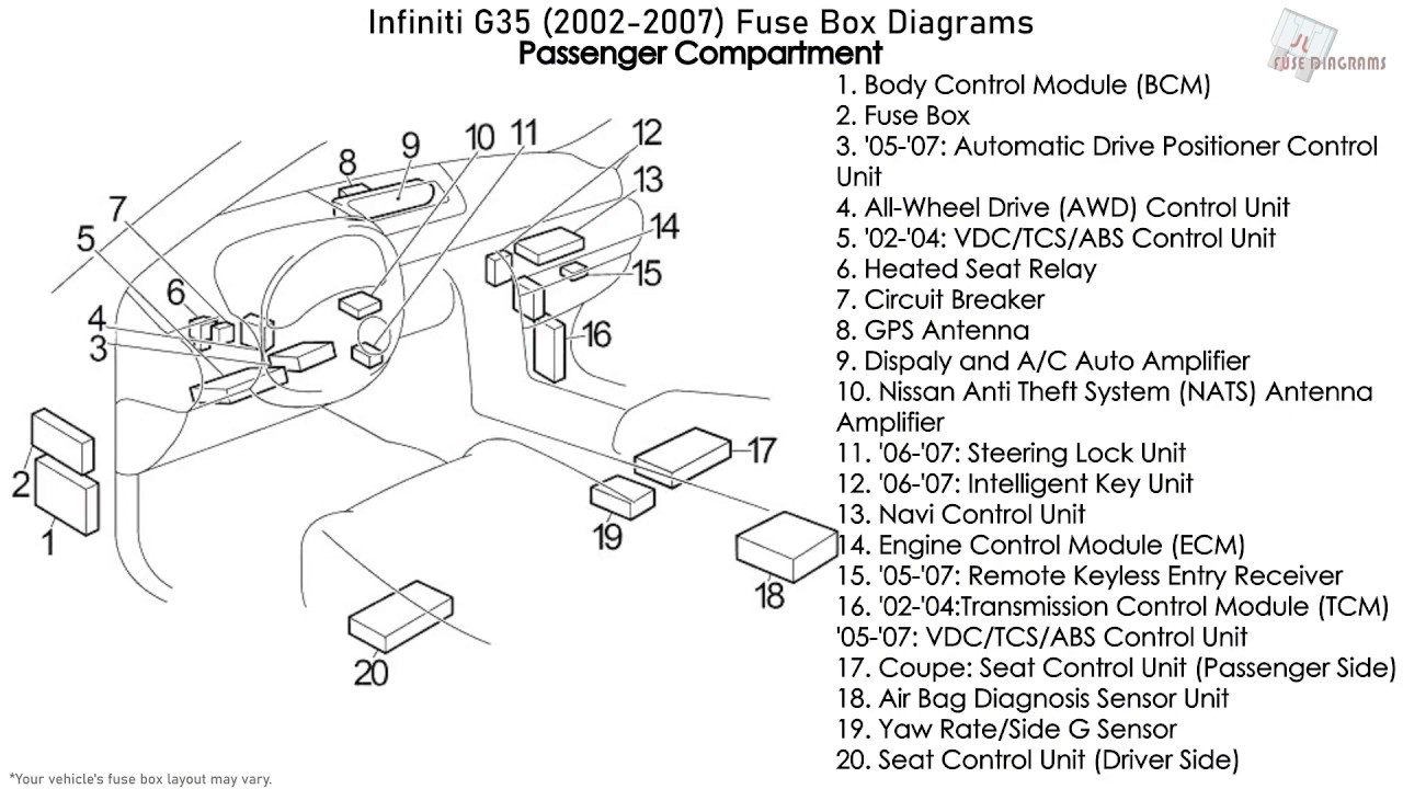
- The Interior Fuse Box: Typically located under the dashboard, often on the driver's side, near the steering column. This box houses fuses for interior components like the audio system, power windows, interior lighting, and various control modules.
- The Engine Bay Fuse Box: Situated in the engine compartment, near the battery. This box protects critical engine management systems, headlights, and other high-current components like the starter motor and radiator fan.
Each fuse box contains fuses and relays. Fuses are sacrificial devices, designed to break a circuit and stop the flow of electricity if the current exceeds a safe level. Relays are electromechanical switches that allow a low-current circuit to control a high-current circuit. For example, the headlight switch uses a low-current signal to activate a relay, which then allows high current to flow to the headlights.
A typical fuse box diagram will show:
- Fuse Location: The physical location of each fuse within the box. This is usually represented by a grid system or a number/letter coordinate.
- Fuse Ampere Rating: The maximum current (measured in Amperes, or Amps) that the fuse can handle before it blows. Common ratings include 5A, 7.5A, 10A, 15A, 20A, 25A, and 30A. It's critical to use a fuse with the correct amperage rating. Using a lower rating will cause nuisance blowing, while a higher rating could allow excessive current to flow, potentially damaging wiring or components.
- Circuit Protected: A brief description of what the fuse protects (e.g., "Headlights (Low Beam)", "Audio System", "Power Windows").
- Relay Location and Function: Similar information for the relays, indicating their position and the circuits they control (e.g., "Headlight Relay", "Fuel Pump Relay").
Understanding Fuse Box Diagram Symbols
The fuse box diagram isn't just a list of words; it uses symbols and conventions to convey information efficiently. Here's a breakdown of some common elements:
- Lines: Solid lines generally represent electrical wiring. Thicker lines might indicate higher-gauge (thicker) wires capable of carrying more current. Dotted lines can represent grounding connections or signal wires.
- Colors: Wire colors are often indicated on the diagram, usually with abbreviations (e.g., "BLU" for Blue, "RED" for Red, "BLK" for Black). This helps you identify specific wires within a harness.
- Fuse Symbols: Fuses are typically represented by a zigzag line enclosed in a rectangle or a simple rectangle with the amperage rating indicated.
- Relay Symbols: Relays are usually shown as a coil with a switch contact. The coil represents the electromagnet that activates the switch.
- Ground Symbols: Ground connections are shown as a series of descending horizontal lines, resembling an upside-down Christmas tree. Proper grounding is essential for the electrical system to function correctly.
It's crucial to consult the specific diagram for your 2007 G35, as there might be slight variations depending on the trim level and options.
How It Works: The Electrical Flow
The fuse box is essentially a distribution center for electrical power. Power from the battery flows into the fuse box, and from there, it's routed to various components throughout the vehicle. Each circuit is protected by a fuse, which is the weakest link in the chain. If a short circuit or overload occurs, the fuse blows, breaking the circuit and preventing damage to other components. Relays act as remotely controlled switches, allowing low-current circuits to control high-current devices. For instance, the starter motor requires a large amount of current to operate. Instead of running a heavy-gauge wire from the ignition switch directly to the starter, a low-current wire from the ignition switch activates a relay, which then allows high current to flow from the battery to the starter motor.
Real-World Use: Basic Troubleshooting Tips
Here's how to use your fuse box diagram for basic troubleshooting:
- Identify the Problem: Determine which component is malfunctioning (e.g., headlights, power windows, radio).
- Consult the Diagram: Locate the fuse or relay associated with the malfunctioning component in the fuse box diagram.
- Inspect the Fuse: Visually inspect the fuse. A blown fuse will usually have a broken filament inside. You can also use a multimeter to check for continuity across the fuse. If there's no continuity, the fuse is blown.
- Replace the Fuse: Replace the blown fuse with a new fuse of the same amperage rating.
- Test the Component: After replacing the fuse, test the component to see if it's working.
- If the Fuse Blows Again: If the new fuse blows immediately or shortly after replacement, there's likely a short circuit or overload in the circuit. This requires further investigation, potentially involving tracing wires and inspecting components.
Important: Never replace a fuse with a higher amperage rating than specified. This can bypass the protective function of the fuse and lead to serious damage or fire.
Safety Considerations
Working with automotive electrical systems can be dangerous. Here are some essential safety precautions:
- Disconnect the Battery: Before working on the electrical system, always disconnect the negative (-) terminal of the battery. This prevents accidental short circuits and electrical shocks.
- Avoid Water: Never work on electrical components in wet conditions.
- Handle Capacitors Carefully: Some electronic modules contain capacitors that can store a charge even after the battery is disconnected. Discharge these capacitors before handling the module.
- Be Aware of High-Current Components: Components like the starter motor and alternator can carry very high currents. Avoid touching these components while the engine is running or the ignition is on.
- Airbags: Exercise extreme caution when working near airbag components. Accidental deployment of an airbag can cause serious injury. Disconnect the battery and wait at least 10 minutes before working on airbag circuits.
Risky components: Anything related to the SRS (Supplemental Restraint System) or airbags, and the ABS (Anti-lock Braking System) require caution. If you are not comfortable troubleshooting these systems, leave it to a qualified technician.
Understanding the 2007 Infiniti G35 fuse box diagram is a valuable skill for any car owner. It empowers you to diagnose and repair electrical problems, add aftermarket accessories safely, and gain a deeper understanding of your vehicle's electrical system. Remember to always prioritize safety and consult the diagram specific to your vehicle.
To further assist you in your electrical endeavors, we have a high-resolution, downloadable diagram of the 2007 Infiniti G35 fuse box available. This resource can be a valuable companion as you navigate the intricacies of your vehicle's electrical system. Happy troubleshooting!