2007 Infiniti M35 Fuse Box Diagram
Alright, let's dive into the fuse box diagram for your 2007 Infiniti M35. This is a crucial piece of information, whether you're chasing down a pesky electrical gremlin, planning a modification, or just aiming to understand your car's inner workings a bit better. Think of it as the roadmap to your M35's electrical system. Having a solid grasp of this diagram can save you a ton of time, money, and potential headaches down the road.
Purpose of the Fuse Box Diagram
Why bother with a fuse box diagram? Simple: it's essential for electrical troubleshooting. Fuses are sacrificial components designed to protect circuits from overcurrents. When a fuse blows, it's interrupting a circuit to prevent damage to more expensive parts. The diagram pinpoints exactly which fuse corresponds to which electrical component or system. This is invaluable for:
- Repairs: Identifying a blown fuse related to a malfunctioning system (e.g., power windows, headlights, audio).
- Modifications: Safely tapping into existing circuits for aftermarket accessories (e.g., adding a dashcam, installing auxiliary lighting). Knowing the amperage rating of a circuit before adding load is *critical*.
- Preventative Maintenance: Understanding the electrical layout of your vehicle and proactively inspecting fuses for signs of wear or corrosion.
- General Knowledge: Expanding your understanding of automotive electrical systems.
Key Specs and Main Parts of the Fuse Box
Your 2007 Infiniti M35 actually has multiple fuse boxes. The primary one is typically located under the hood, often near the battery or on one of the fender wells. There's also a secondary fuse box inside the cabin, usually under the dashboard on the driver's side. Some models may have a third in the trunk or near the rear seats. The diagram we're focusing on will cover both the under-hood and in-cabin fuse boxes.
Key specs you need to be aware of:
- Fuse Ampere Rating (Amperage): This is the amount of current a fuse can handle before it blows. It's indicated by a number on the fuse itself (e.g., 5A, 10A, 20A). Always replace a blown fuse with one of the *exact* same amperage rating. Using a higher amperage fuse can cause serious damage to the circuit it’s supposed to protect.
- Fuse Type: The M35 uses various types of fuses, including blade fuses (ATO/ATC), mini blade fuses, and potentially some cartridge fuses for higher amperage circuits. The diagram will specify the type for each fuse location.
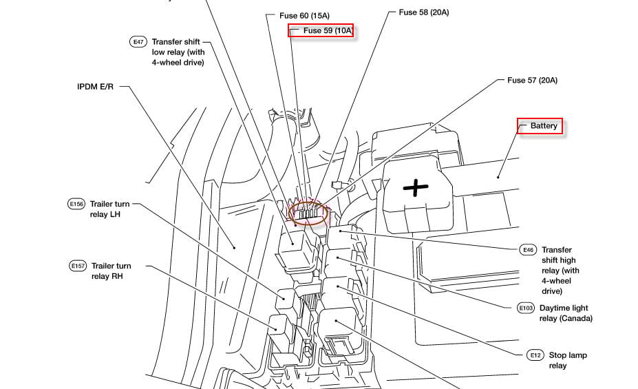
- Relay Locations: Relays are electromechanical switches that control higher-current circuits. The diagram will indicate the location and function of each relay in the fuse box. Relays often control components like the fuel pump, headlights, and starter motor.
- Fuse Box Cover: The inside of the fuse box cover usually has a simplified version of the fuse diagram. This is a quick reference, but the full diagram is more detailed and accurate.
Understanding the Symbols in the Diagram
Fuse box diagrams use symbols and notations to represent different components and connections. Here's a breakdown of some common symbols:
- Fuses: Represented by a small rectangular box with a number inside (the amperage rating).
- Relays: Represented by a square or rectangular symbol, sometimes with a coil symbol inside.
- Lines: Solid lines indicate direct electrical connections. Dashed lines may indicate ground connections or less critical paths.
- Colors: Wire colors are often indicated next to the lines connecting components. Understanding wire colors can be helpful for tracing circuits outside the fuse box. You might see abbreviations like BLU (blue), RED (red), BLK (black), etc.
- Icons: Icons are used to represent the function of the circuit protected by a fuse. For example, a headlight icon indicates the headlight circuit, a window icon indicates the power window circuit, etc.
Pay close attention to the legend or key provided with the diagram. This will explain the specific symbols and abbreviations used in that particular diagram. Different manufacturers may use slightly different conventions.
How It Works: Following the Circuit
The fuse box is the central distribution point for electrical power in your car. Power from the battery is routed to the fuse box, and then distributed to various circuits throughout the vehicle. Each circuit is protected by a fuse of the appropriate amperage rating.
To understand how it works, imagine a simple circuit: Battery -> Fuse -> Switch -> Light Bulb -> Ground -> Battery. If there's a short circuit (e.g., a wire chafes and touches the chassis), the current will surge. This excessive current will cause the fuse to blow, breaking the circuit and preventing damage to the wiring, switch, and light bulb.
The diagram helps you trace this circuit by showing which fuse is connected to the light bulb's switch, the amperage rating of that fuse, and the wire colors involved.
Real-World Use: Basic Troubleshooting Tips
Here's how you can use the fuse box diagram to troubleshoot common electrical problems:
- Identify the Symptom: What's not working? (e.g., headlights, power windows, radio).
- Consult the Diagram: Locate the fuse that corresponds to the malfunctioning system.
- Inspect the Fuse: Visually inspect the fuse. A blown fuse will typically have a broken filament. Sometimes it can be hard to see, so using a multimeter to check for continuity across the fuse is a more reliable method.
- Replace the Fuse: If the fuse is blown, replace it with a new fuse of the *same* amperage rating.
- Test the System: After replacing the fuse, test the system to see if it's working again.
- If the Fuse Blows Again: If the new fuse blows immediately or shortly after being replaced, this indicates a short circuit or overload in the circuit. Do not keep replacing fuses! This is a symptom of a bigger problem that needs further investigation. You’ll need to trace the wiring, inspect components, and potentially use a multimeter to diagnose the issue.
Important Note: Before replacing any fuses, disconnect the negative terminal of the battery. This will prevent accidental short circuits while you're working. Always double-check the diagram to ensure you're replacing the correct fuse.
Safety: Risky Components
Working with electrical systems can be dangerous. Be particularly cautious when dealing with:
- High-Amperage Fuses and Relays: These often control critical systems like the fuel pump, starter motor, and ABS. Mishandling these can cause serious damage or even injury.
- Airbag System Fuses: The airbag system is extremely sensitive. Incorrectly replacing or tampering with airbag system fuses can lead to accidental deployment, which can be very dangerous. If you suspect an issue with your airbag system, it's best to consult a qualified technician.
- Main Power Fuses: These protect the entire electrical system. Shorting these out can cause significant damage and even a fire.
Always disconnect the negative battery terminal before working on the electrical system. If you're not comfortable working with electrical components, it's best to take your car to a qualified mechanic.
Remember, a blown fuse is a symptom, not the root cause. While replacing it might temporarily fix the problem, it's crucial to address the underlying issue that caused the fuse to blow in the first place.
Now you know what to look for and can better understand the fuses and diagrams for your 2007 Infiniti M35.
We have the complete fuse box diagram for your 2007 Infiniti M35 available for download. It’s a high-resolution file you can print out and keep handy in your garage or toolbox. Download the diagram by clicking here.