2007 Jeep Grand Cherokee Radio Wiring Diagram
Understanding the 2007 Jeep Grand Cherokee's radio wiring diagram is crucial for a variety of tasks, ranging from simple speaker upgrades to troubleshooting electrical issues or even installing a new aftermarket head unit. This article will provide a detailed breakdown of the wiring diagram, equipping you with the knowledge to confidently tackle radio-related projects on your WJ Grand Cherokee.
Purpose and Significance
The radio wiring diagram is essentially a roadmap of your vehicle's audio system. Its primary purposes include:
- Repairing Existing Issues: Identifying faulty wiring, shorts, or open circuits within the radio system.
- Upgrading Components: Safely and correctly installing new speakers, amplifiers, or subwoofers.
- Installing Aftermarket Head Units: Adapting the factory wiring harness to accommodate a new radio unit with different pinouts and functionalities.
- Learning Vehicle Electrics: Providing a foundational understanding of how the audio system integrates with the vehicle's overall electrical architecture.
Key Specs and Main Parts of the 2007 Grand Cherokee Radio System
The 2007 Jeep Grand Cherokee (WJ Generation) offered several audio system options, typically including a base model radio, a premium system with an amplifier, and sometimes a navigation system. The wiring diagram will vary slightly depending on which system your vehicle has. Here are some key components and considerations:
- Head Unit (Radio): The control center of the audio system, responsible for receiving signals (AM/FM, CD, etc.), processing audio, and sending output to the speakers.
- Speakers: Typically, the Grand Cherokee has speakers in the front doors, rear doors (if equipped), and possibly tweeters in the dashboard. Impedance is important here, and most factory speakers are 4 ohms.
- Amplifier (if equipped): The amplifier boosts the audio signal from the head unit to provide more power to the speakers. It's usually located under a seat or in the rear cargo area.
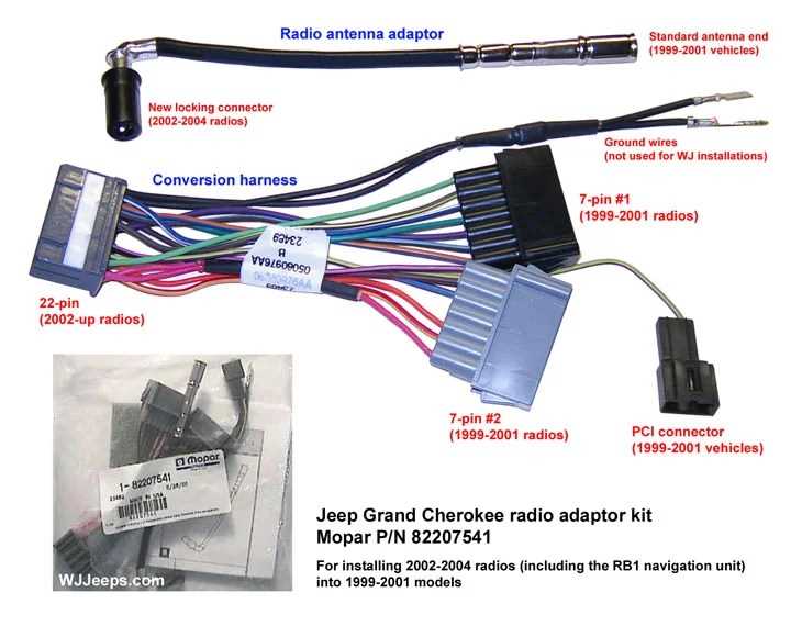
- Wiring Harnesses: Bundles of wires that connect the various components of the audio system. These use a standardized connector to plug into the back of the radio.
- Antenna: Receives radio signals.
- CAN Bus (Controller Area Network): In some higher-end systems, the radio communicates with other vehicle systems via the CAN bus. This allows for features like steering wheel audio controls.
- Ground Connections: Essential for completing the electrical circuit. Poor ground connections are a common source of audio problems.
Decoding Wiring Diagram Symbols
Understanding the symbols used in the wiring diagram is crucial for interpreting the information accurately. Here's a breakdown of common elements:
- Lines: Represent wires. Thicker lines may indicate higher current-carrying capacity.
- Colors: Each wire is color-coded (e.g., red for power, black for ground, green for speaker wires). The diagram will have a key explaining the color codes. It is imperative to use a multimeter to confirm wire functions, as colors may fade or vary slightly over time.
- Icons/Shapes: Represent components like speakers, resistors, capacitors, fuses, and connectors. Standardized electrical symbols are used.
- Numbers/Letters: Indicate wire gauge (thickness) and circuit numbers for identification. Wire gauge is important for ensuring adequate current flow.
- Connectors: Shown as squares or rectangles with pins inside. The diagram will often identify the connector number and pin number within the connector.
A typical wiring diagram section will show the radio itself, often labeled "Head Unit" or "Radio," with lines branching out to various connectors and components. Each line will be color-coded, and the diagram will specify which pin on the connector corresponds to that wire.
How the Radio System Works
The basic flow of the radio system is as follows:
- Power is supplied to the head unit, typically from the vehicle's battery through a fuse and an ignition-switched circuit.
- The head unit receives audio signals from various sources (AM/FM antenna, CD player, auxiliary input).
- The head unit processes the audio signal and sends it to the speakers (directly or through an amplifier).
- If an amplifier is present, it boosts the signal and sends it to the speakers.
- Speakers convert the electrical signal into sound waves.
- Control signals from the steering wheel (if equipped) are sent to the radio via the CAN bus or dedicated wiring.
The CAN bus is a serial communication protocol that allows different electronic control units (ECUs) within the vehicle to communicate with each other. In the context of the radio, it might be used to control volume, change stations, or display information on the instrument cluster.
Real-World Use: Basic Troubleshooting Tips
Here are some common issues and how the wiring diagram can help you diagnose them:
- No Power to Radio: Check the fuses associated with the radio. Use the wiring diagram to trace the power supply wire back to the battery and ignition switch. Verify voltage with a multimeter. A fuse protects the circuit from overcurrent.
- No Sound from Speakers: Check the speaker connections. Use the wiring diagram to identify the speaker wires and test for continuity (using a multimeter) between the head unit and the speaker. The speaker itself might be damaged.
- One Speaker Not Working: Could be a blown speaker, a loose connection, or a break in the speaker wire. Swap the speaker with one that works to diagnose the problem.
- Interference or Static: Check the antenna connection. Ensure the ground connections are clean and secure. Interference can also be caused by other electrical components in the vehicle.
- Steering Wheel Controls Not Working: Check the CAN bus connection to the radio. The wiring diagram will show the CAN bus wires. This often requires a specialized aftermarket adapter if installing a non-OEM radio.
Before performing any electrical work, disconnect the negative terminal of the battery. This prevents accidental shorts and potential damage to the vehicle's electrical system.
Safety Considerations
Working with automotive electrical systems can be dangerous if not done properly. Here are some important safety precautions:
- Disconnect the Battery: Always disconnect the negative terminal of the battery before working on the electrical system.
- Use a Multimeter: Use a multimeter to test for voltage and continuity before making any connections. This will help you avoid accidental shorts.
- Protect Wires: Use electrical tape or heat shrink tubing to insulate exposed wires.
- Avoid Working on Live Circuits: Never work on a circuit while the vehicle is running or the ignition is on unless absolutely necessary for testing.
- Be Careful with Airbags: The airbag system is a sensitive electrical system. Avoid disturbing any airbag wiring or components.
- High-current circuits, particularly those related to the amplifier (if equipped), can be dangerous. Always disconnect the battery and exercise extreme caution.
Radio Wiring Diagram Access
Having the correct wiring diagram for your specific 2007 Jeep Grand Cherokee radio is paramount. The systems vary based on options. We have access to this diagram, complete with color codes and pinouts, which you can download. This will provide the detailed visual aid you need to safely and effectively work on your Jeep's audio system.