
2007 Mustang Gt 02 Sensor Wiring Harness
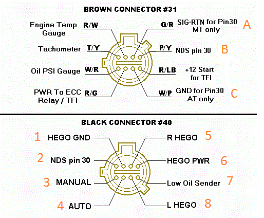
Alright, let's dive into the 2007 Mustang GT's oxygen sensor wiring harness. This article will provide a detailed walkthrough, covering its purpose, key specs, how it functions, and how to troubleshoot common issues. This information is invaluable whether you're tackling a repair, planning modifications, or simply expanding your automotive knowledge.
Why Understanding the O2 Sensor Wiring Diagram Matters
The oxygen (O2) sensors are critical components in your Mustang GT's engine management system. They provide feedback to the Powertrain Control Module (PCM, the car's computer) about the oxygen content in the exhaust gas. This information is used to fine-tune the air-fuel mixture, optimizing engine performance, fuel efficiency, and minimizing emissions. A faulty O2 sensor or a damaged wiring harness can lead to a host of problems, including poor gas mileage, rough idling, engine misfires, and a dreaded check engine light. Having access to and understanding the wiring diagram is essential for:
- Diagnosis and Repair: Pinpointing wiring faults, shorts, or open circuits that cause sensor malfunctions.
- Modification and Upgrades: Safely installing aftermarket components, such as headers or performance O2 sensors.
- Preventative Maintenance: Identifying potential wiring issues before they escalate into major problems.
- Learning and Understanding: Gaining a deeper understanding of your Mustang's engine management system.
Key Specs and Main Parts
The 2007 Mustang GT utilizes four O2 sensors: two upstream (pre-catalytic converter) and two downstream (post-catalytic converter). These sensors are typically of the zirconium dioxide (ZrO2) or titania (TiO2) type. The upstream sensors are crucial for fuel trim adjustments, while the downstream sensors primarily monitor the catalytic converter's efficiency.
Key Specifications:
- Sensor Type: Zirconium dioxide (ZrO2) is the most common type in 2007 Mustangs.
- Sensor Location: Two upstream (Bank 1 Sensor 1, Bank 2 Sensor 1) and two downstream (Bank 1 Sensor 2, Bank 2 Sensor 2). "Bank 1" refers to the side of the engine containing cylinder number 1.
- Wiring: Typically four-wire configuration.
- Voltage Range: 0-1 Volt (typical for ZrO2 sensors; output voltage corresponds to oxygen levels in the exhaust).
Main Parts:
- O2 Sensors: The sensing element itself, responsible for measuring oxygen content.
- Wiring Harness: The bundle of wires connecting the O2 sensors to the PCM and other electrical components. This includes the sensor connector itself.
- Connectors: The plugs that connect the O2 sensors to the wiring harness.
- PCM (Powertrain Control Module): The engine's computer that receives signals from the O2 sensors and adjusts fuel trim.
- Heated Circuit: All O2 sensors on the 2007 Mustang GT are heated, using a heater element to quickly bring the sensor to operating temperature. This ensures accurate readings, especially during cold starts.
Understanding the Wiring Diagram Symbols
A wiring diagram uses standardized symbols to represent electrical components and connections. Here’s a breakdown of the common symbols you’ll encounter in a 2007 Mustang GT O2 sensor wiring diagram:
- Lines: Solid lines represent wires. Dashed lines may indicate shielded wires or connections within a component. The thickness of the line doesn't usually indicate wire gauge.
- Colors: Each wire is assigned a color code (e.g., WT/RD for White with a Red stripe). Matching these colors is crucial for proper connections.
- Circles/Dots: A filled circle or dot indicates a wire connection (splice). An empty circle usually means the wires cross but are not connected.
- Rectangles: Typically represent electrical components, like relays or the PCM.
- Ground Symbol: Represents the ground connection, typically a series of horizontal lines decreasing in length.
- Connector Symbols: Illustrate the shape and pin arrangement of connectors, showing how wires are plugged together.
Color Codes: Understanding the color codes is crucial. The first color is the base color of the wire, and the second (if present) is the stripe color. Common codes include: BK (Black), BN (Brown), BU (Blue), DG (Dark Green), GY (Gray), LG (Light Green), OG (Orange), PK (Pink), RD (Red), TN (Tan), VT (Violet), WH (White), YE (Yellow).
How It Works
The O2 sensors work based on the principle that there's a voltage difference between the inside and outside of the sensor due to differences in oxygen concentration. Let's break down a typical four-wire O2 sensor circuit:
- Two Wires for the Heater Circuit: These wires provide power and ground to the sensor's internal heater. The PCM controls the heater to maintain the sensor at its optimal operating temperature (around 600°F or 315°C). This ensures fast and accurate readings.
- Signal Wire: This wire carries the voltage signal from the sensor to the PCM. The voltage varies depending on the oxygen content in the exhaust. A higher voltage indicates a richer mixture (less oxygen), while a lower voltage indicates a leaner mixture (more oxygen).
- Ground Wire: Provides a ground path for the sensor signal.
The PCM constantly monitors the voltage signals from the upstream O2 sensors. Based on these signals, it adjusts the fuel injectors' pulse width (the amount of time they stay open) to fine-tune the air-fuel ratio. The downstream O2 sensors primarily monitor the efficiency of the catalytic converters. If the downstream sensors detect similar oxygen levels to the upstream sensors, it indicates that the catalytic converter is not functioning properly.
Real-World Use: Basic Troubleshooting Tips
If you're experiencing O2 sensor-related issues, here are some basic troubleshooting steps you can take, using the wiring diagram as your guide:
- Visual Inspection: Carefully inspect the wiring harness and connectors for any signs of damage, such as frayed wires, cracked insulation, or corroded connectors.
- Voltage Testing: Use a multimeter to check for proper voltage at the O2 sensor connector. Refer to the wiring diagram to identify the correct pins for the heater circuit, signal wire, and ground. Check that the heater circuit is receiving the expected voltage (typically battery voltage, around 12V).
- Continuity Testing: Use a multimeter to check for continuity between the O2 sensor connector and the PCM connector. This verifies that the wires are intact and not broken.
- Resistance Testing: Check the resistance of the O2 sensor heater element. An excessively high or low resistance reading indicates a faulty heater.
- Scan Tool Diagnostics: Use an OBD-II scan tool to read diagnostic trouble codes (DTCs) related to the O2 sensors. This can provide valuable clues about the nature of the problem. Note: A code like P0131 could refer to "O2 Sensor Circuit Low Voltage (Bank 1, Sensor 1)."
- Check for Exhaust Leaks: Exhaust leaks near the O2 sensors can introduce false readings, leading to incorrect fuel trim adjustments. Carefully inspect the exhaust system for any leaks.
Example: If you get a code related to the heater circuit, use the wiring diagram to identify the heater circuit wires. Test for voltage at the connector with the engine running. If there's no voltage, trace the wiring back to the relay or fuse that powers the heater circuit. The wiring diagram will help you identify these components.
Safety Considerations
Working with automotive electrical systems can be dangerous. Here are some safety precautions to keep in mind:
- Disconnect the Battery: Always disconnect the negative battery terminal before working on the electrical system to prevent short circuits and electrical shocks.
- Work in a Well-Ventilated Area: Exhaust fumes are toxic. Ensure adequate ventilation when working on the exhaust system.
- Wear Safety Glasses: Protect your eyes from debris and chemicals.
- Use Proper Tools: Use the correct tools for the job, and ensure they are in good working condition.
- Be Cautious Around Hot Components: The exhaust system can get extremely hot. Allow it to cool down before working on it.
- Wiring Hazards: Exercise caution when dealing with wires near the exhaust system. High temperatures can melt insulation and create electrical hazards.
Remember: The O2 sensors operate at high temperatures and can be extremely hot after the engine has been running. Allow them to cool down completely before handling them.
With the right knowledge and tools, you can effectively diagnose and repair O2 sensor wiring issues on your 2007 Mustang GT. Understanding the wiring diagram is the first step towards mastering your car's engine management system.
We have the 2007 Mustang GT O2 sensor wiring diagram file available for download. Good luck with your project!