2007 Nissan Versa Fuse Box Diagram
Alright, let's dive into the 2007 Nissan Versa fuse box diagram. This isn't just some glorified map; it's your roadmap to electrical troubleshooting, modification, and general understanding of your Versa's inner workings. Whether you're tracking down a phantom drain, upgrading your sound system, or just trying to figure out why your windshield wipers decided to take a permanent vacation, this diagram is your friend.
Purpose: Why You Need This Diagram
Why bother with a fuse box diagram? Several good reasons:
- Troubleshooting Electrical Problems: The most obvious reason. A blown fuse is a common culprit for a variety of electrical issues. The diagram helps you quickly identify the fuse associated with the malfunctioning circuit.
- Preventing Further Damage: Replacing a blown fuse with the wrong amperage can lead to serious damage to your vehicle's electrical system and potentially start a fire. The diagram ensures you use the correct replacement.
- Adding Aftermarket Accessories: Installing new lights, a stereo system, or other electronic gadgets often involves tapping into existing circuits. The diagram helps you identify suitable circuits and avoid overloading them.
- Understanding Your Car's Electrical System: Even if you're not currently experiencing any problems, studying the diagram can give you a better understanding of how your Versa's electrical system is laid out and how different components are interconnected.
Key Specs and Main Parts
The 2007 Nissan Versa actually has two main fuse boxes: an interior fuse box, typically located under the dashboard on the driver's side, and an engine compartment fuse box, usually near the battery. Each box protects different circuits, and their diagrams will be different.
- Interior Fuse Box: This typically handles circuits related to interior components such as the radio, lights (interior and exterior), power windows, power locks, instrument cluster, and the ECM (Engine Control Module).
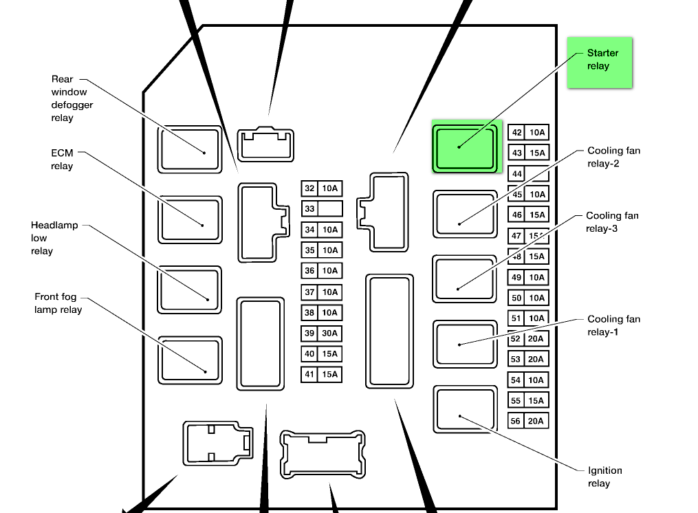
- Engine Compartment Fuse Box: This box protects circuits related to the engine, transmission, cooling system, headlights, horn, and other vital components under the hood.
Within each fuse box, you'll find:
- Fuses: These are the sacrificial lambs of the electrical system. They're designed to break the circuit when the current exceeds a safe level, protecting more expensive components. Fuses are rated in amperes (amps or A), which indicates the amount of current they can handle before blowing.
- Relays: Relays are electrically operated switches. They use a small current to control a larger current. They're used to switch high-power circuits like headlights, starters, and fuel pumps.
- Circuit Breakers: Some circuits use circuit breakers instead of fuses. These are resettable overcurrent protection devices. If a circuit breaker trips, it can be reset manually after the fault is corrected.
Symbols: Decoding the Diagram
The fuse box diagram isn't just a random collection of lines and numbers; it uses a standardized set of symbols to represent different components and connections. Here’s a breakdown:
- Lines: Lines represent electrical wires. Thicker lines generally indicate higher current-carrying capacity.
- Boxes: Boxes represent fuses, relays, and other components. The number inside the box typically corresponds to the fuse or relay number.
- Numbers: Numbers alongside the boxes indicate the fuse amperage rating. For example, "15A" means a 15-amp fuse.
- Component Symbols: Different symbols represent specific components. Common symbols include:
 Fuse
Fuse