
2007 Pontiac G6 Exhaust System Diagram
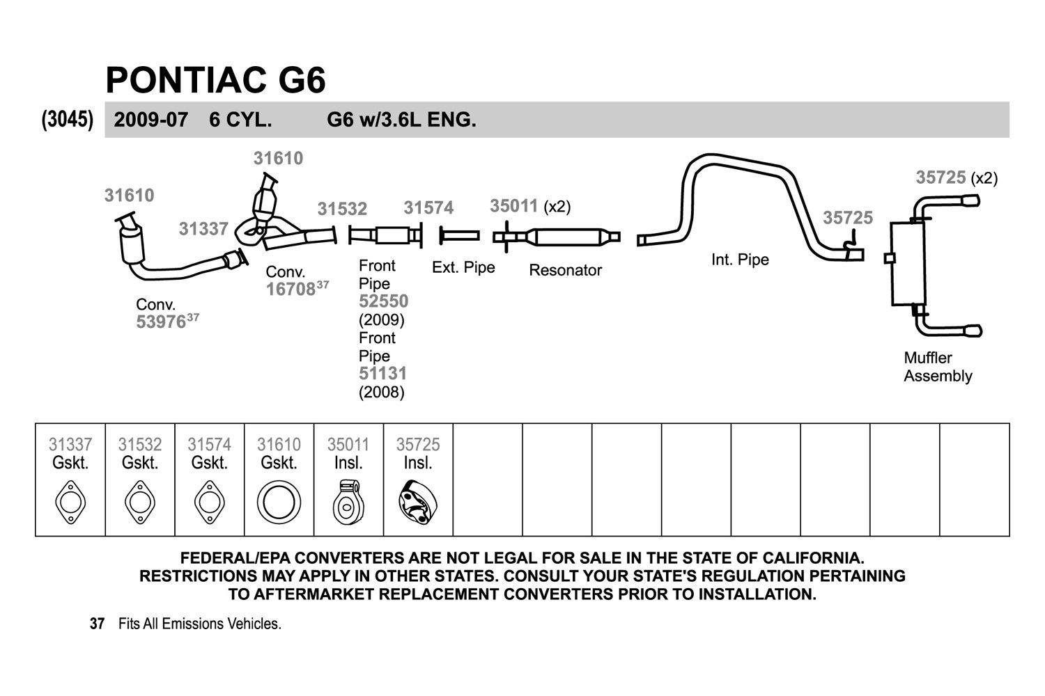
For the intermediate car owner, modder, or DIY mechanic, understanding your vehicle's exhaust system is crucial. This article dissects the 2007 Pontiac G6 exhaust system using a diagram-centric approach, offering a technical yet approachable guide. We'll cover the components, function, safety aspects, and basic troubleshooting, allowing you to tackle repairs, modifications, or simply expand your automotive knowledge.
Purpose of Understanding the 2007 Pontiac G6 Exhaust System Diagram
An exhaust system diagram isn't just a pretty picture; it's a vital tool. It serves multiple purposes:
- Repairs and Maintenance: Identifying the correct component location when replacing a rusted muffler, leaky exhaust manifold gasket, or faulty oxygen sensor becomes significantly easier.
- Troubleshooting: Pinpointing the source of exhaust leaks, rattling noises, or poor engine performance is often expedited with a visual representation.
- Modifications: Planning and executing exhaust system upgrades, such as installing a cat-back system or high-flow catalytic converter, requires a clear understanding of the existing layout and dimensions.
- Learning and Education: Comprehending the flow of exhaust gases and the function of each component enhances your overall automotive knowledge.
Key Specs and Main Parts
The 2007 Pontiac G6 came with several engine options, which slightly affect the exhaust system configuration. Common engine types are the 2.4L I4, the 3.5L V6, and the 3.9L V6. While the principles remain the same, the number of exhaust manifolds (one for I4, two for V6) and the specific routing of the exhaust pipes will differ.
Here's a breakdown of the core components typically found in the G6 exhaust system:
- Exhaust Manifold(s): Bolted directly to the engine cylinder head(s), the manifold collects exhaust gases from each cylinder and channels them into a single pipe. Aftermarket headers can be installed in place of stock manifolds to improve exhaust flow.
- Catalytic Converter: A crucial emissions control device that uses catalysts to convert harmful pollutants (hydrocarbons, carbon monoxide, and nitrogen oxides) into less harmful substances (water, carbon dioxide, and nitrogen). Federal law mandates their presence and functionality.
- Oxygen (O2) Sensors: These sensors monitor the oxygen content in the exhaust gas stream. The upstream sensor (before the catalytic converter) provides feedback to the engine control unit (ECU) for air-fuel mixture adjustments. The downstream sensor (after the catalytic converter) monitors the converter's efficiency.
- Resonator: A chamber designed to reduce specific sound frequencies, contributing to overall exhaust noise reduction.
- Muffler: The primary sound-deadening component of the exhaust system, using baffles and sound-absorbing materials to quiet the exhaust flow.
- Exhaust Pipes: The tubes connecting the various exhaust components, typically made of steel.
- Hangers and Mounts: Rubber or metal supports that secure the exhaust system to the vehicle's undercarriage, preventing vibrations and damage.
- Gaskets and Flanges: Seals that prevent exhaust leaks between components.
Understanding Exhaust System Diagram Symbols
Diagrams are usually stylized to indicate the function and connection point of each component. Let's clarify common symbols:
- Solid Lines: Represent exhaust pipes. The thickness of the line might indicate the pipe's diameter.
- Dashed Lines: Usually indicate vacuum lines associated with emissions controls or related systems, though less prevalent in the core exhaust layout.
- Boxes or Rectangles: Generally denote components like the catalytic converter, resonator, or muffler. They may contain internal details or a simplified representation.
- Circles: Often symbolize sensors, such as oxygen sensors. A small connector symbol might indicate the sensor's electrical connection.
- Triangles: Might point out the direction of flow.
- Colors: While not universally standardized, colors can differentiate between different types of pipes or materials. For instance, a different color might be used to signify a stainless steel component versus a standard steel component.
- Fasteners: Symbols showing bolts, nuts, and flanges indicate connection points and the hardware required for assembly.
How the Exhaust System Works
The exhaust system's primary function is to safely remove combustion byproducts from the engine. The process unfolds as follows:
- Exhaust Gas Collection: Exhaust gases exit the engine cylinders and enter the exhaust manifold(s).
- Catalytic Conversion: The exhaust gases pass through the catalytic converter, where pollutants are converted into less harmful substances.
- Sound Reduction: The resonator and muffler dampen exhaust noise, making the vehicle quieter.
- Exhaust Gas Release: The remaining exhaust gases are expelled through the tailpipe.
- Sensor Feedback: Oxygen sensors monitor the composition of the exhaust gases, providing feedback to the ECU for optimal engine performance and emissions control.
Real-World Use: Basic Troubleshooting
Here are some common exhaust system problems and how a diagram can aid in troubleshooting:
- Exhaust Leaks: A hissing or rumbling sound, especially near joints, indicates an exhaust leak. The diagram helps you locate flanges, gaskets, and pipe sections where leaks are common. Check for rust or cracks.
- Rattling Noises: Rattling often indicates a loose heat shield, a broken exhaust hanger, or internal damage within the muffler or catalytic converter. The diagram assists in identifying the location of these components.
- Reduced Engine Performance: A clogged catalytic converter can restrict exhaust flow, leading to reduced power. The diagram highlights the converter's location for inspection. Scan tool data from the O2 sensors will help determine if the converter is functioning efficiently.
- Check Engine Light (CEL): Codes related to oxygen sensors (e.g., P0171, P0420) often point to exhaust system problems. The diagram shows the sensor locations, allowing you to inspect their wiring and connections. Always address CEL issues promptly to prevent further damage.
Safety Considerations
Working on an exhaust system presents several safety hazards:
- Heat: Exhaust components can be extremely hot, even long after the engine has been turned off. Allow the system to cool completely before working on it. Use heat-resistant gloves.
- Exhaust Fumes: Exhaust gases contain carbon monoxide, a deadly odorless gas. Always work in a well-ventilated area.
- Jack Stands: Never work under a vehicle supported only by a jack. Use properly rated jack stands to secure the vehicle.
- Sharp Edges: Exhaust pipes can have sharp edges or burrs. Wear gloves to protect your hands.
- Catalytic Converter: While less immediate than heat, catalytic converters can contain harmful materials. Avoid breathing in dust if you are removing one.
- Eye Protection: Rust and debris can fall from the exhaust system. Wear safety glasses to protect your eyes.
Important Note: Modifying or removing emissions control devices, such as the catalytic converter, may be illegal in your area. Always check local regulations before making any modifications.
With this information and a detailed diagram in hand, you're well-equipped to understand, maintain, and even modify your 2007 Pontiac G6's exhaust system. You can now proceed confidently with your car projects.
We have the detailed 2007 Pontiac G6 Exhaust System Diagram available for download.